

Nov. 06, 2026
Expanding an operating rack battery bank changes more than its nameplate capacity. First establish whether the present shortfall is stored energy, continuous current, a short power peak, or a limit elsewhere in the system. Then determine whether the installed modules are healthy and whether the exact new and old models and versions may share a bank. An added branch changes the DC current paths, protection, rack loading, battery communication, and possibly inverter settings. The expansion is complete only after the revised bank is recognized and behaves acceptably under representative charge and discharge conditions. Voltage and rack space alone do not establish compatibility.
Additional parallel modules can increase stored energy and potentially the bank's available current, but they solve a shortage only when the battery is the limiting part of the system. A runtime shortfall and a power shortfall require different evidence. Energy is the accumulated power demand over time; current is what the bank must deliver at a particular moment, at the voltage then present. Adding nameplate kilowatt-hours may extend a modest load while leaving a brief high-power event unsupported.

Plot or reconstruct the load over a representative duty cycle. A load that runs normally but stops early after a long discharge points toward usable energy. A bank that reaches a BMS discharge limit when equipment starts, although substantial charge remains, points toward instantaneous current. Compare demand at the battery side of the inverter, including conversion losses, with the existing modules' allowed continuous and peak discharge values. The minimum operating voltage matters: the same power requires more current as DC voltage falls. The module rating, BMS limits, main DC path, and inverter limit must all permit that current. Discover's AES Rackmount manual distinguishes continuous, one-hour, and peak current ratings; those are different tests of a proposed expansion, not interchangeable figures.
If the inverter, charger, transfer equipment, or load behavior reaches its limit first, adding battery modules does not eliminate that bottleneck. The usable system capability is bounded by the lowest relevant limit along the energy path. An inverter with a fixed output rating cannot supply a larger AC load merely because more DC energy sits behind it. Likewise, extra battery capacity cannot make a charger accept a higher charge current than it is rated or configured to deliver.
Use alarms and measurements to distinguish a battery trip from an inverter overload. If the inverter limits first, address that device. If the bank reaches a BMS limit first, compatible modules may reduce per-module current, provided the DC and control paths support them.
The existing bank should have a stable, explainable operating baseline before a new module is attached. An unresolved module alarm, repeated dropout, abnormal branch current, or persistent voltage or state-of-charge divergence is a reason to resolve the old-bank problem first. Otherwise the new module may mask a fault at light load while the fault reappears during charging or a larger discharge.
Review the bank's recent behavior under known loads, not just its idle display. Record which modules were online, their reported state of charge, temperatures if available, BMS alarms, and branch currents through a meaningful discharge and recharge. A momentary difference after a load transition is not the same as one module repeatedly carrying much less current or reaching its cutoff first. The latter may indicate unequal electrical paths, a module limit, or a deteriorated module. The observation should lead to a specific investigation of the old group rather than a blanket decision that a new module will balance it.
Age and use history matter because resistance and usable capacity can diverge. A stable baseline lets the commissioning team attribute later alarms or unequal current to the addition rather than guessing from the expanded bank alone.
Model, hardware and firmware version, state of charge, and resting voltage can change whether and how modules may be connected. There is no safe cross-brand voltage-difference or charge-percentage rule. The applicable instruction is the one covering the exact combination being added, together with the condition of the installed bank.
The contrast among published instructions illustrates why nominal voltage is insufficient. The Discover AES Rackmount manual specifies same-model requirements and a close voltage match before paralleling in its system. The EG4 LifePower4 expansion guide calls for its batteries to be charged individually before an addition to an existing rack. Victron's Lithium NG installation instructions allow differing age or capacity for certain parallel arrangements within that product family. These examples establish that the allowable preparation varies; none is a compatibility rule for a Wirentech module or mixed banks.
Where the supported combination requires charge or voltage alignment, follow its instructions before closing the branch. A state-of-charge display alone does not establish equal resting voltage after recent operation.
Only a combination of models and revisions explicitly permitted by the applicable product documentation should proceed toward a common bank; any required firmware and control settings must also match that rule. Equal nominal voltage is a necessary electrical starting point for a parallel arrangement, not proof that the batteries' BMS limits, charge behavior, alarms, and communication roles will work together. If the combination is explicitly prohibited, use a separate supported arrangement. If its key compatibility conditions are unknown, direct connection remains unestablished.

Modules sharing a DC bus can still have different BMS limits or disconnect at different states of charge. A communicating bank may also need a defined controller to report aggregate limits. The permitted combination must cover this coordinated behavior, not merely physical connection.
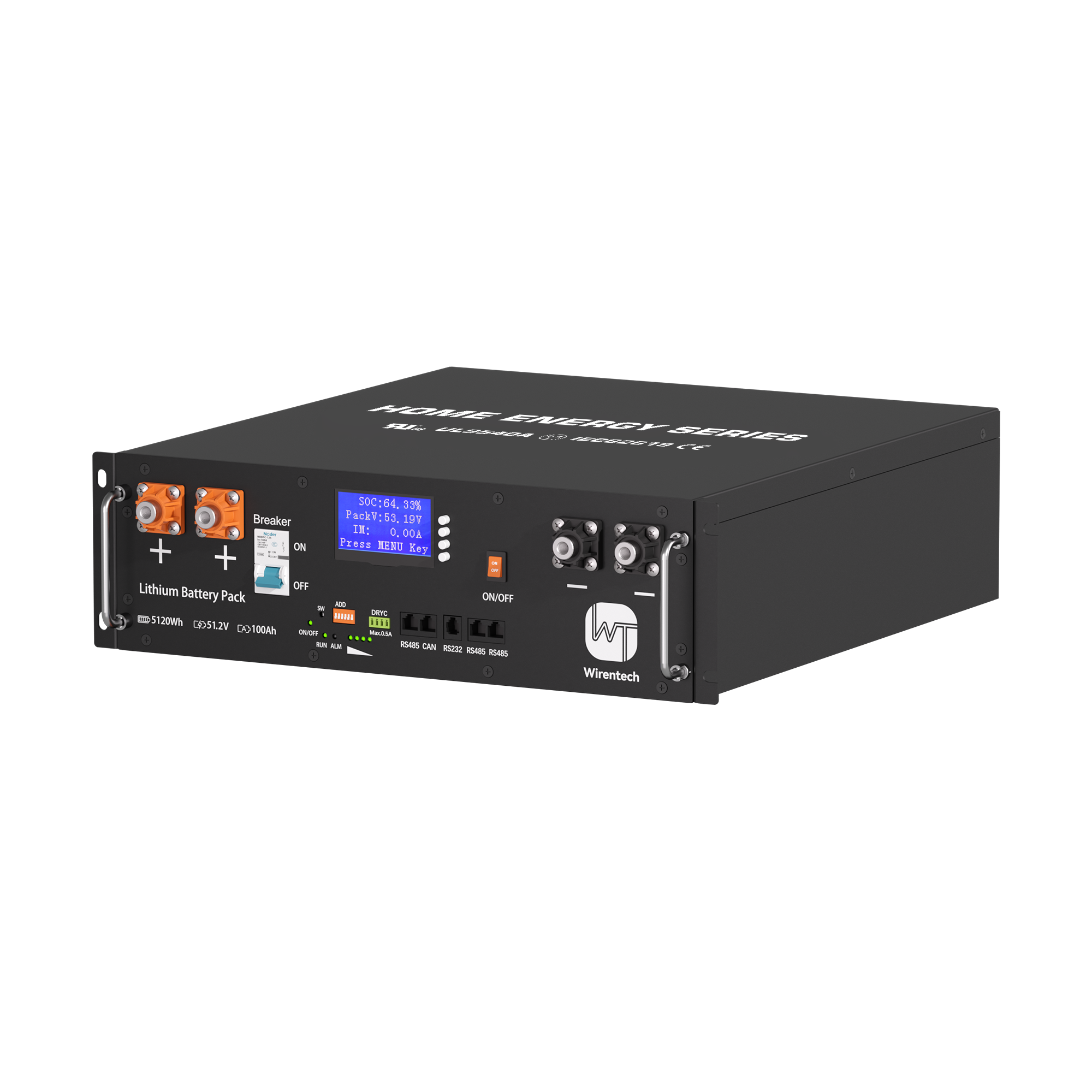
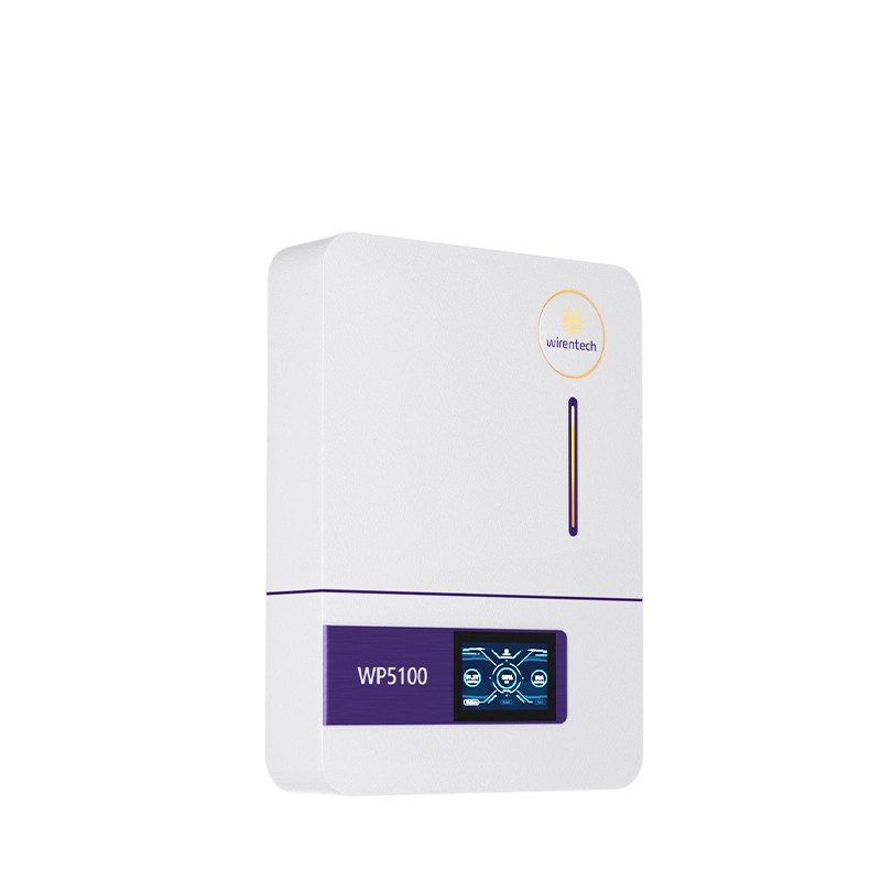
When comparing a candidate module with the installed group, use the exact family and revision covered by the manufacturer. The WT5100 51.2V rack battery specifications provide publicly listed model details and an interface starting point; they do not establish that WT5100 can join a particular existing bank.
A different generation needs explicit rules for mixed operation, including firmware, module ordering or addressing, and the controlling BMS role. A later housing or similar capacity does not show that its messages and current limits have the same interpretation as the installed generation. In a mixed control chain, the inverter may see an incomplete or misleading aggregate limit even while all battery terminals are live.
For example, EG4's LL-S instructions for particular combinations specify a master position, firmware conditions, and address sequence. Those details show the kind of dependency a mixed-generation bank can have; their ID assignments are not a generic setup recipe. If the exact combination is supported, follow its own configuration and revision rules and observe all modules during recommissioning. If no rule covers the combination, the outcome is not “probably compatible because voltage matches.” It is a different system design decision, such as using a supported homogeneous bank or a separately managed group.
The new branch changes both positive and negative current paths, and may increase the aggregate current the busbars, main cables, protection devices, disconnect, and inverter terminals must carry. Each element must remain suitable for the revised operating and fault conditions. A free rack slot or a spare busbar stud is not a current rating.
Trace the proposed branch from the new module's positive and negative terminals through its branch protection to the appropriate busbars, then through the main protection and DC connection. Record the ratings and connection limits along that actual route. A branch device protects its branch; it does not automatically make an undersized shared bus or main cable acceptable. The permitted continuous and short-duration currents of the batteries and inverter determine the design load, while the protective devices and cable installation method determine what can be safely carried. The applicable electrical design and product instructions govern sizes and coordination; a universal cable gauge or fuse value would be misleading here.
Adding one branch can also change current sharing among the old modules. Cable lengths, cross sections, contact quality, and bus connection positions contribute resistance. Victron's Wiring Unlimited battery-bank chapter demonstrates why apparently parallel paths can carry different currents. If the old DC path was sized only for the original bank, redesign it before energizing the addition.

An empty rack position establishes only possible vertical space. It does not establish load capacity, mounting compatibility, cable bend space, ventilation, or access to the new branch protection and connectors. The additional module and hardware must fit the cabinet and preserve the clearances required by their actual installation instructions.
Account for module mass and how its rails or shelf transfer weight to the rack. A module can fit by height yet force a tight conductor bend or inaccessible disconnect. Check airflow and service access with doors and panels in their operating positions. Published module dimensions do not certify the installed rack.
The battery data network and inverter controls must recognize the added module and its supported operating limits. A DC connection supplies a power path; it does not assign a communication address, update a master module, increase a configured module count, or revise an inverter charge or discharge limit. The exact changes depend on the supported product family and control topology.
Treat the DC circuit and BMS communication chain as two distinct networks. The batteries' terminals may meet at busbars while data runs through module-to-module links, a master BMS, a hub, or another approved arrangement. The modules may need unique addresses, a particular sequence, compatible firmware, or a revised aggregation setting. Product instructions such as EG4's rack-battery addressing examples demonstrate these possibilities, but they are not instructions for another brand. At the inverter, a closed-loop system may use reported limits and state of charge, whereas a different arrangement may use configured voltage and current limits. The new physical capacity is useful only to the extent that the actual control configuration can operate it correctly.
Bus voltage and illuminated module displays show that at least part of the DC path is energized. They do not show that every module is participating in BMS coordination or that the inverter is using the expanded bank's correct limits. A silent module may supply or absorb current while remaining invisible to the controller, or it may be isolated despite an apparently normal system voltage.
If four modules are installed but only three appear in the BMS view, resolve the address or link problem. If the inverter retains its old limit, the bank may gain runtime without the expected power capability. Do not raise that limit merely because another module is visible: the DC path and product limits must support it.
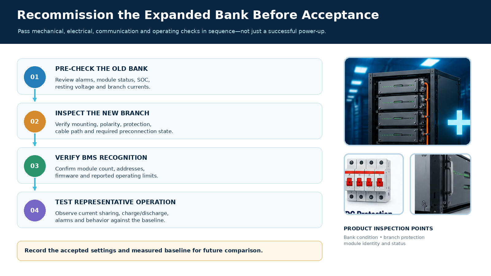
Recommissioning should move through controlled isolation, static electrical checks, BMS and inverter recognition, and then representative charging and discharging. Passing one layer does not replace the next: correct polarity does not prove communication, and correct communication does not prove acceptable current sharing under load. Use the exact equipment's isolation, switching, torque, and precharge instructions for physical work; those operations cannot be safely generalized across modules and inverters.
Before energizing the new branch, confirm the completed mechanical installation, polarity, branch protection, cable connections, and the preconnection module state required by its manufacturer. After the approved start sequence, check for new alarms and verify that the controller sees the intended module count and limits. Begin observation at a controlled load, then use a representative duty cycle rather than only an idle display. Compare individual branch currents and module states with the old-bank baseline. The goal is explainable sharing within each product's limits, not mathematically identical current at every instant. The Victron Lithium NG installation guidance illustrates separate installation and BMS checks for its own products; its component values and sequence must not be copied to an unrelated bank.
The decision table puts the expansion conditions beside the resulting action so a failed layer can be traced before acceptance.
| Expansion condition | Observed state | Decision | Next action |
|---|---|---|---|
| Module combination | Exact old and new versions are explicitly covered by the applicable parallel rule | Continue to the state and hardware checks | Retain the covered firmware and configuration; do not generalize the rule to other models |
| Existing-bank condition | A persistent old-module alarm or unexplained voltage or state-of-charge spread remains | Do not use the addition as a repair | Resolve the old-bank abnormality before connecting the new branch |
| DC path | The added branch or potential aggregate current exceeds a rated cable, bus, disconnect, or protective path | Do not energize the revised arrangement | Redesign the limiting path and its protection for the applicable load and fault conditions |
| Control chain | The added module is absent from the BMS view or reported limits and addresses disagree | DC connection alone has not completed integration | Correct the supported address, firmware, or control configuration |
| Representative operation | Persistent branch overcurrent, module dropout, or BMS alarm appears during a relevant load or charge test | Expansion has not passed recommissioning | Stop acceptance and isolate the branch or control cause before retesting |
Record the settings and observations that determined acceptance so later changes in alarms, current distribution, or runtime are interpretable.
A module that repeatedly drops offline, a persistent branch current disparity that drives one module into a limit, a BMS alarm, or an inverter limit inconsistent with the recognized bank means the expansion has not passed. Do not accept it solely because the new module powers on or the total bus voltage looks correct. The failure points toward different causes: a DC path problem, a module state or compatibility problem, or a communication and setting problem.
Observe the pattern under both a relevant discharge and, where permitted, a relevant charge condition. Current need not be exactly equal at every moment, since module state and path resistance differ, but each branch should remain within its allowed limits and behave consistently with the supported arrangement. A transient immediately after a load change may settle; a recurring imbalance or protective trip requires investigation. If recognition fails, examine the communication chain before increasing load. If recognition is sound but one branch carries unexpectedly high current, return to its cable path, connection quality, and module condition. If the inverter imposes the old configured limit, correct that setting only within the verified battery and DC-path capability. Retest the condition that originally motivated expansion; otherwise an apparently successful installation may leave the reader's real shortfall unresolved.
Related News

Nov. 07, 2026
Can a Home Battery Start and Run High-Surge Household Loads?
Learn why battery kWh alone cannot prove motor-start backup. Compare inverter surge duration, running demand, simultaneous loads and a supervised backup test.
Nov. 07, 2026
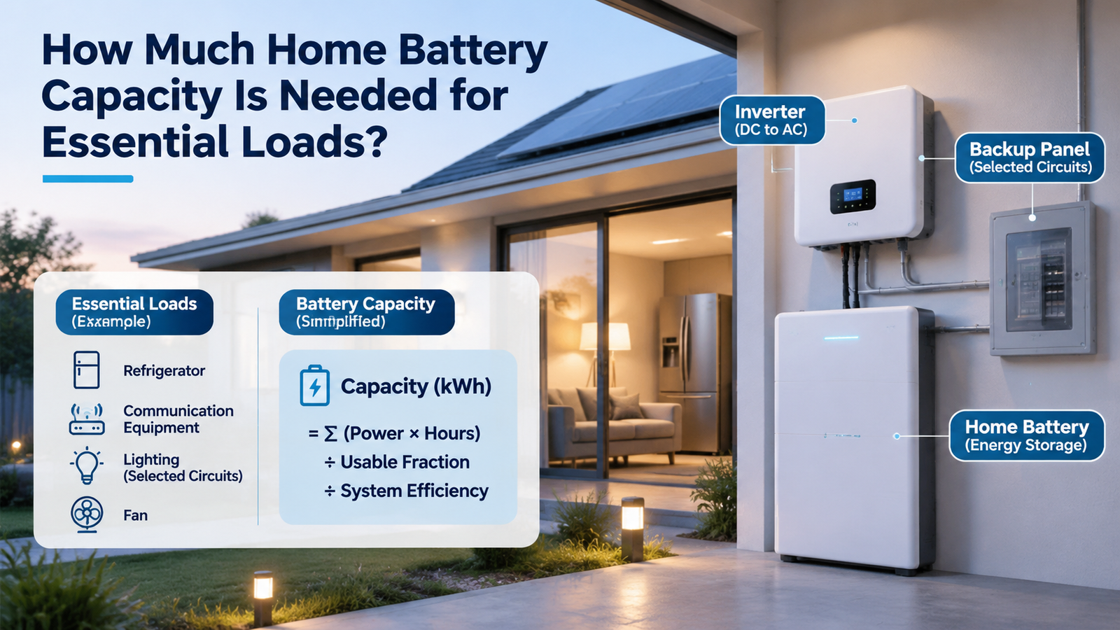
How Much Home Battery Capacity Is Needed for Essential Loads?
Calculate home battery capacity from essential-load power, duty cycle and outage hours. See a transparent kWh example and avoid double-counting losses.

Nov. 07, 2026
How Should a Home Battery Specification Sheet Be Read for Backup and Daily Use?
Compare home battery capacity, usable energy, continuous and peak output, charging limits and rating conditions before judging daily use or backup claims.
Nov. 06, 2026
Whole-Home Battery Backup or Critical-Load Backup: Which Scope Fits the Home?
Compare whole-home and critical-load battery backup by protected circuits, peak power, outage duration and load control to choose a realistic home backup scope.
Nov. 06, 2026
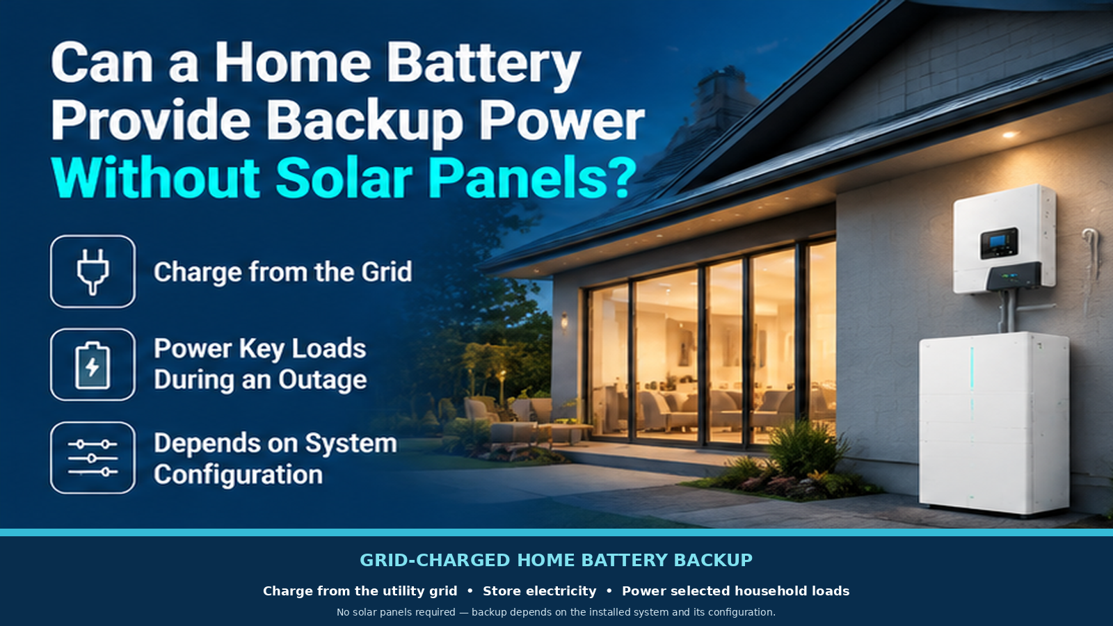
Can a Home Battery Provide Backup Power Without Solar Panels?
A home battery can provide backup without solar if grid charging, outage isolation and backup circuits are configured. Learn what limits runtime and recharge.

Nov. 06, 2026
How Does a Home Battery Storage System Work for a Household?
Follow the energy path through a home battery, inverter and controls. Learn how charging, daily discharge and outage backup differ before comparing systems.

Nov. 06, 2026
How Can A Weak Battery Be Distinguished From A Weak Golf Cart Battery Bank?
Compare like-conditioned unit and bank readings to separate one weak battery from broad bank loss, charging shortfall or connection trouble.
Nov. 06, 2026
How Should A Replacement Golf Cart Battery Bank Be Planned?
Decide whether one unit or the bank needs replacement, then specify voltage, fit, connections and first-charge checks before ordering.

Nov. 06, 2026
What Changes When A Golf Cart Battery Bank Is Converted To Lithium?
Map the battery bank, tray, charger, controller, gauge and accessory interfaces that change when converting a lead-acid golf cart to lithium.

Nov. 06, 2026
When Does Lithium Make Sense Instead Of Lead Acid For A Golf Cart?
Compare lithium and lead acid for the same golf-cart duty, charging routine, maintenance capacity and ownership horizon before deciding whether a switch is worthwhile.

Nov. 06, 2026
How Can Peak Current Demand Be Matched To A Golf Cart Battery?
Compare a golf cart’s acceleration and hill-load current by duration with battery continuous, pulse and protection ratings under matching conditions.