

Sep. 14, 2026
Server rack battery backup must be sized from an outage objective and a verified load profile. First define which IT loads must remain online, for how long, during which failures, and with what recovery sequence. Then calculate delivered energy, confirm continuous and transient power, and coordinate the battery with the UPS or power-conversion equipment, distribution, bypass, protection, monitoring, and maintenance plan. A battery module alone does not create a resilient backup system.
The engineering focus is server-room runtime and resilience, not general rack-battery product selection. Success is measured by whether the protected service behaves as intended through normal operation, an outage, a component fault, maintenance, and restoration.
Start with business and technical consequences. Identify services that cannot stop, services that may shut down in sequence, and loads that can be shed immediately. Define the maximum acceptable interruption and whether the system must bridge a generator start, complete an orderly shutdown, or sustain a longer outage.
Create operating states rather than one “backup” label:
Each state needs an owner and a pass condition. This prevents a nominal runtime target from hiding the fact that the wrong loads are connected or that the system cannot be maintained without interruption.
Inventory servers, storage, network devices, security systems, cooling components, controls, and any auxiliary equipment powered from the protected distribution. Record real operating demand where possible, including high-activity periods and planned growth. Name the measurement boundary: equipment input, PDU output, UPS output, or another defined point.
Energy for a simple planning case can be expressed as load power multiplied by required hours. Then account for conversion losses, reserve policy, battery operating limits, temperature, and aging using project-approved assumptions. Do not convert nominal battery energy directly into promised runtime.
|
Runtime input |
Typical source |
Failure if omitted |
|
Protected load by circuit |
Metering, PDU data, equipment records |
Oversizing or protecting the wrong loads |
|
Required support time |
Continuity plan |
Runtime target does not match operations |
|
Conversion path |
UPS/inverter documentation |
Losses and limits are ignored |
|
Reserve and shutdown point |
Operating policy |
No controlled margin for recovery |
|
Growth allowance |
Approved capacity plan |
New servers consume the design margin |
Use a range of load cases rather than one average. Minimum load affects long-runtime behavior; typical load supports planning; peak simultaneous load checks power and thermal limits.
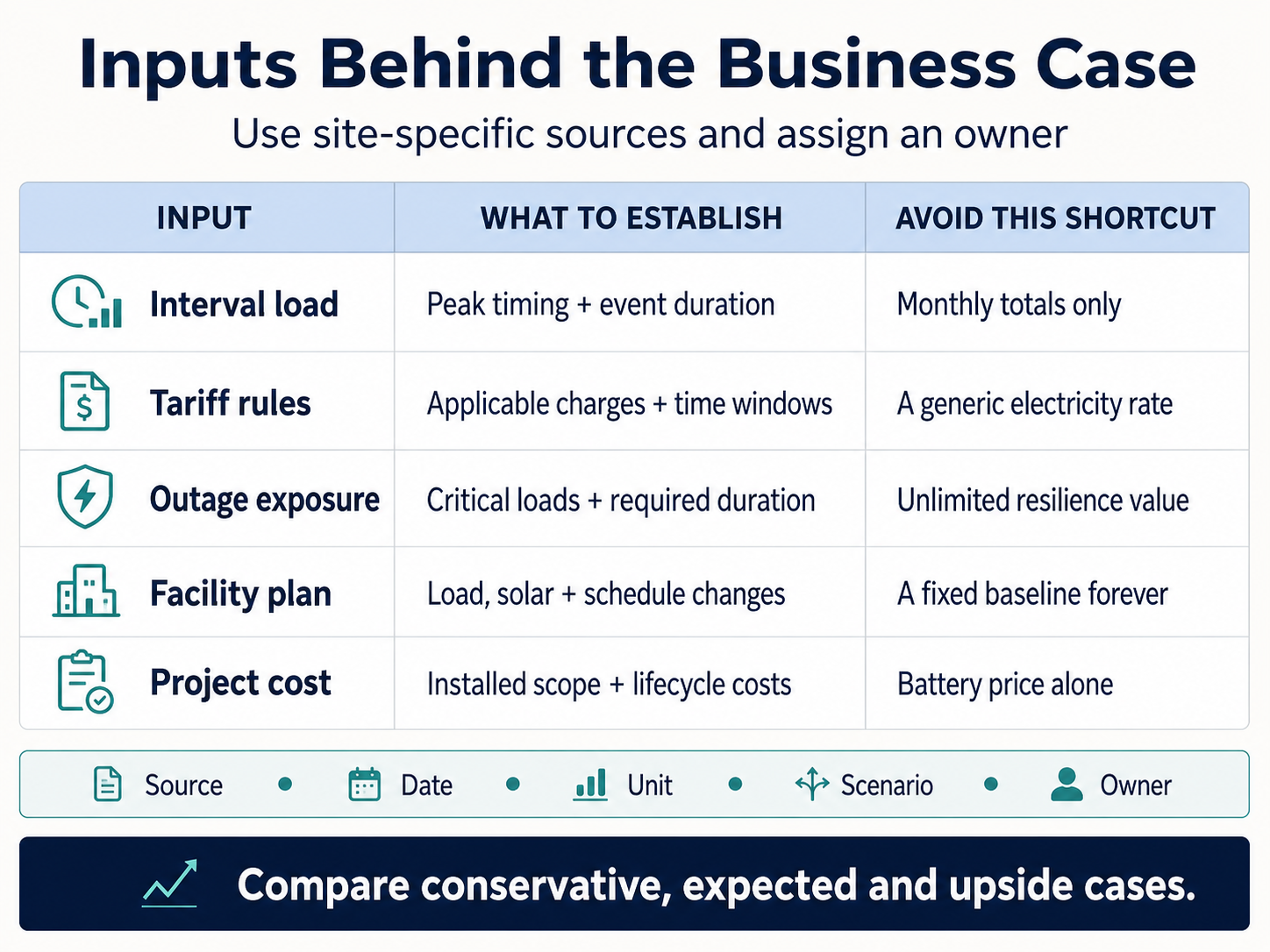
Energy answers how long the system can operate. Power answers whether it can support the load at a moment in time. A battery may contain enough nominal kilowatt-hours yet still be unsuitable if current, voltage sag, inverter limits, cables, connectors, or protection cannot carry the load.
Check continuous demand, short transient events, recharge power, and concurrent charge/load conditions. Keep kilowatts and kilowatt-hours separate in every table. When a product name contains a power figure, obtain the controlled document before treating it as continuous or peak.
For DC current planning, power divided by voltage provides a starting estimate, but the engineer must use the applicable voltage range and efficiency assumptions. Current rises as voltage falls for a given power demand. That affects conductor size, voltage drop, connector heating, branch protection, and busbar design.
Redundancy only exists when a failure can be isolated without losing the required service. Two battery strings connected to one unprotected bus may still share the same failure point. “N+1” should identify the unit of redundancy, the design load, the unavailable component, and the operating state that must continue.
Map common-mode risks across battery modules, BMS control, busbars, contactors, DC protection, UPS power stages, bypass, cooling, monitoring, and upstream/downstream distribution. Decide which failures require an automatic response and which require operator intervention.
|
Architecture question |
Evidence required |
Acceptance test |
|
What may fail without dropping the load? |
One-line and failure analysis |
Isolate the defined component under controlled conditions |
|
How is maintenance performed? |
Bypass and isolation procedure |
Demonstrate safe transfer and return |
|
What happens on communication loss? |
Control narrative and settings |
Observe fallback, alarm, and recovery |
|
How is reserve protected? |
Shutdown and load-shed logic |
Confirm sequence at the agreed threshold |
|
How is a failed branch contained? |
Protection coordination |
Test or review model-scoped evidence |
The UPS or power-conversion equipment defines a DC operating window, charge behavior, current limits, alarms, and shutdown logic. The battery defines its own operating range and protective response. These envelopes must overlap across temperature, state of charge, load, and recharge conditions.
If communications are used, validate the exact protocol, pinout, firmware, settings, and control ownership. CAN or RS485 on both devices does not prove that messages or limits are compatible. If operation is voltage-based without communications, document how charge, discharge, reserve, and fault behavior are controlled and monitored.
Also check startup and black-start behavior. Some systems require an external supply or a specific sequence after full shutdown. Test restoration after utility loss, low-state-of-charge shutdown, protection trip, and maintenance isolation so operators know which actions are automatic and which require authorized intervention.
Server rooms already manage heat, airflow, access, cable density, and fire/life-safety requirements. Adding batteries changes mass distribution, service clearances, DC cabling, isolation, and emergency procedures. Confirm rack support, floor loading, lifting path, module removal, cable bend radius, separation, ventilation, and environmental conditions.
Do not assume that an IT rack is suitable because a battery is “rack mounted.” Use the battery drawing and support requirements, then assess the completed rack. Keep isolation and labels accessible. A service technician should be able to identify and disconnect the correct branch without moving live adjacent equipment.
Local electrical, building, fire, and occupational requirements must be determined for the installation market. Transport evidence such as UN 38.3 does not approve an installed system. UL 1973 component evidence for one model cannot be transferred to another battery. Ask for the exact documents and scope required by the project.
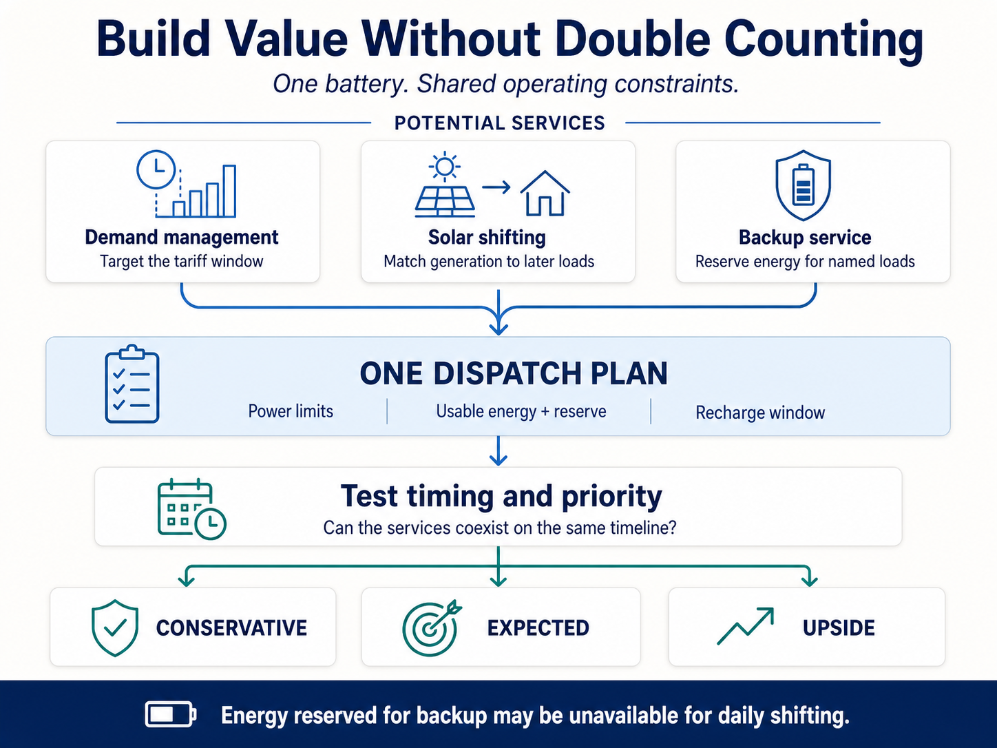
Commissioning should prove the operating story, not just confirm that indicators are green. Freeze equipment models, serials, firmware, settings, wiring, protection, and load boundary. Calibrate or identify the instruments used.
Run tests in a controlled sequence:
Record what was actually demonstrated. A calculated two-hour runtime is not the same as a witnessed two-hour test, and neither should be represented as the other.
The baseline will change as servers are added, firmware is updated, UPS equipment is replaced, settings are adjusted, or battery modules age. Establish change triggers: load growth above a defined threshold, repeated alarms, major firmware updates, battery replacement, topology changes, and failed capacity or runtime checks.
Maintain an as-built register containing the one-line, rack layout, models, serials, firmware, settings, protocol files, protection details, test records, supported-load list, reserve policy, and recovery procedures. The operator should know who can change settings and how to return the system to its approved state.
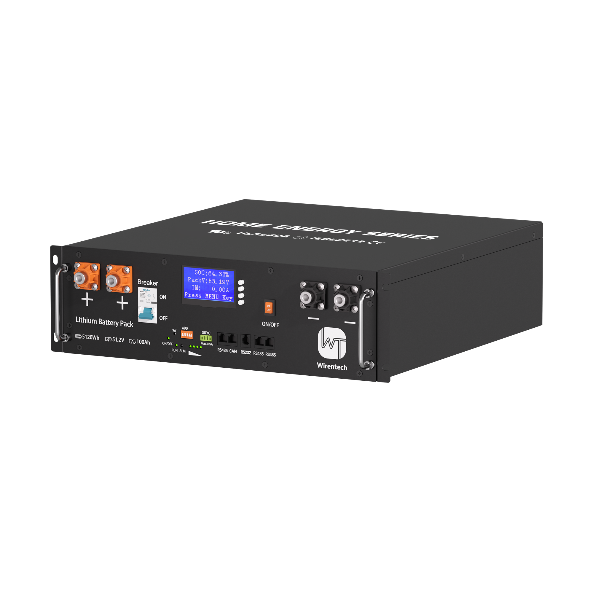
A rack-mounted battery product page can identify a candidate format, but it cannot prove server-room runtime, continuous output, UPS compatibility, cycle life, certification, or warranty. Those decisions require controlled model-specific documents and testing of the complete backup architecture.
Before purchase, turn the candidate into a model-scoped record: exact designation, voltage and current limits, nominal energy, mechanical drawing, communication files, protection behavior, applicable evidence, and approved commercial terms. Any missing field remains an open qualification item rather than an assumed benefit.
Measure the protected load and multiply power by required runtime, then apply approved loss, reserve, temperature, and aging assumptions. Validate the result against the battery and UPS operating envelopes.
No. Extra nominal energy does not correct insufficient power, incompatible voltage, weak protection, poor thermal design, or a common-mode failure. Evaluate the complete architecture.
It means the required load and operating objective can still be met with one defined unit unavailable. Name that unit, load, duration, and failure state; then demonstrate the claim.
No. Verify exact device models, firmware, protocol, wiring, settings, message behavior, alarms, and validation date.
Both serve different purposes. Calculation supports design; controlled testing demonstrates the installed configuration under stated conditions. Record the basis of each result.
Requirements depend on product, system, installation, and jurisdiction. Request model-scoped files and have the project’s qualified parties confirm what applies; do not treat transport testing as installation approval.
Provide as-built drawings, equipment and serial register, settings, firmware, protocol records, test logs, alarm and recovery procedures, maintenance plan, applicable evidence, and approved warranty terms.
The correct server rack battery backup is the architecture that protects named loads through defined failures and returns them to service predictably. Runtime, power, redundancy, UPS control, room constraints, testing, and operational ownership must agree; a battery label cannot close those interfaces.
For a project review, send the measured load by circuit, required autonomy, growth plan, UPS model and firmware, one-line diagram, rack and room conditions, redundancy objective, destination market, quantity, and the outage scenarios that commissioning must demonstrate.
Related News
Sep. 14, 2026
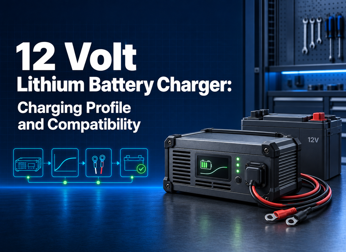
12 Volt Lithium Battery Charger: Charging Profile and Compatibility
Match a 12 volt lithium battery charger to battery voltage, current, termination, BMS response, temperature, connector, and acceptance tests.
Sep. 14, 2026
Rack Mount Battery: Rack-Mounted Battery Product Selection
Specify a rack mount battery by electrical limits, rack geometry, BMS behavior, protection, communications, sample tests, and production controls.
Sep. 14, 2026
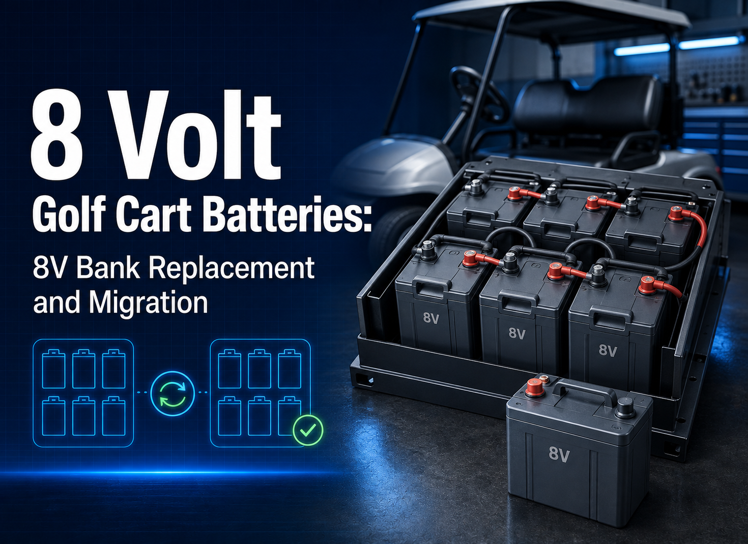
8 Volt Golf Cart Batteries: 8V Bank Replacement and Migration
Evaluate 8 volt golf cart batteries by bank architecture, vehicle duty, charger fit, cable layout, pilot evidence, and fleet replacement scope.
Sep. 14, 2026
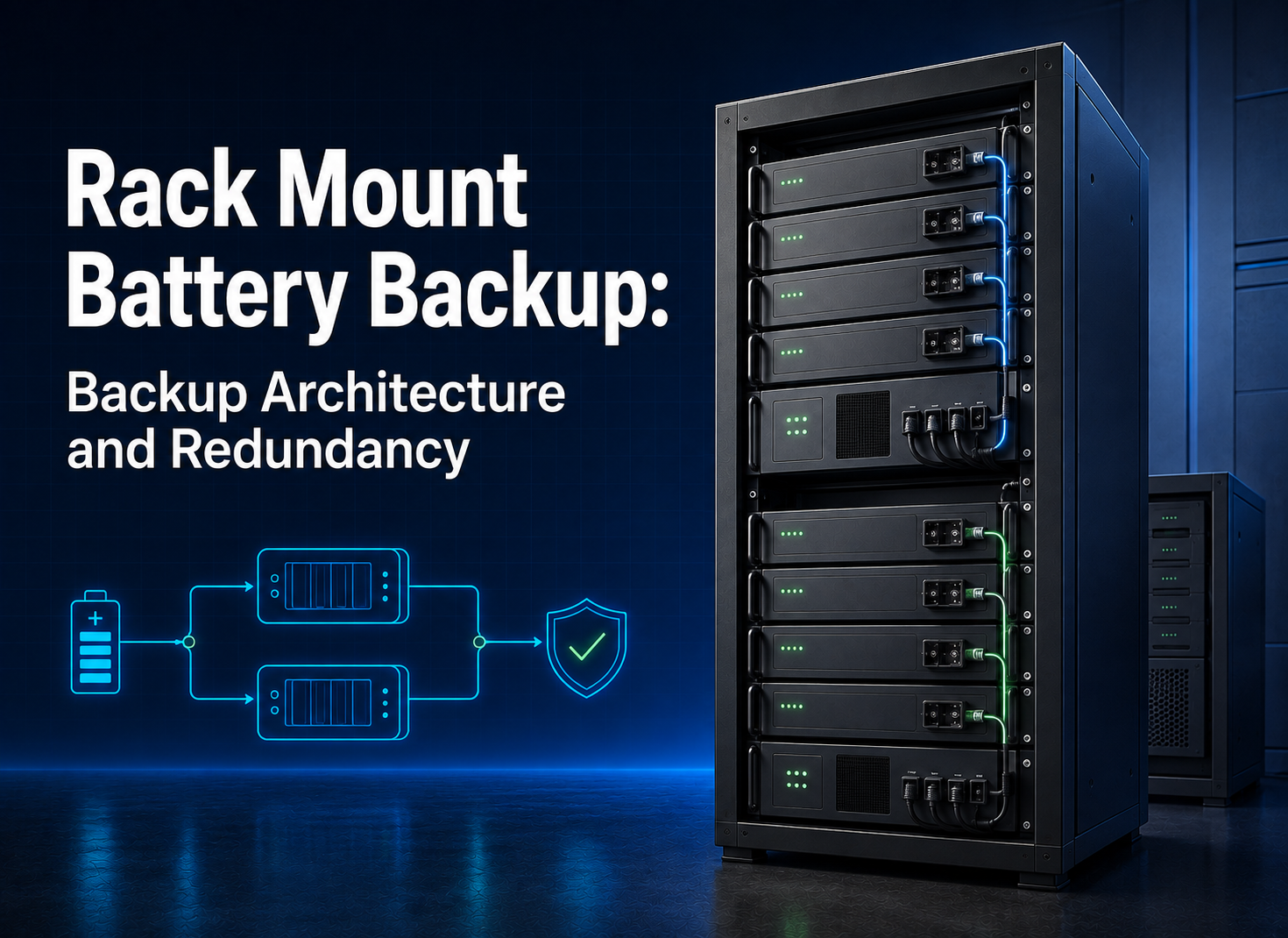
Rack Mount Battery Backup: Backup Architecture and Redundancy
Design rack backup around operating states, N+1 definitions, branch isolation, bypass, current sharing, degraded-state tests, and change control.

Sep. 04, 2026
Solar Server Battery Rack for Sale: RFQ Specification
Build a solar rack-battery RFQ around duty data, inverter interface, rack and protection scope, evidence, commercial comparison, FAT, and SAT.
Sep. 04, 2026
Rack Battery Charger: Charging Interface Design Guide
Specify a rack battery charger by charge envelope, AC/DC interfaces, BMS control, protection, thermal design, testing, and RFQ evidence.
Aug. 28, 2026
Powerwall Installation: From Site Survey to Commissioning
Plan a Powerwall installation through site survey, structural and electrical design, compatibility checks, permits, commissioning tests, and handover records.
Aug. 28, 2026
Commercial Battery Storage: Business Case & Buyer Guide
Build a commercial battery storage business case from load data, tariff logic, resilience value, system boundaries, evidence, delivery risk, and acceptance criteria.
Aug. 27, 2026
Server Rack Battery: A B2B Selection Framework
Use a decision framework to shortlist server rack battery options by duty, voltage, energy, rack envelope, BMS behavior, evidence, and commercial fit.
Aug. 27, 2026
48V Server Rack Battery: 48V Platform Selection and Integration
Evaluate a 48V server rack battery by voltage window, usable energy, DC current, rack fit, communications, commissioning evidence, and supplier controls.

Aug. 27, 2026
Custom LiFePO4 Batteries for RV and Golf Cart OEM Projects
Plan custom LiFePO4 batteries for RV and golf cart OEM projects by separating duty cycles, voltage, capacity, enclosure, controls, validation, and RFQ terms.