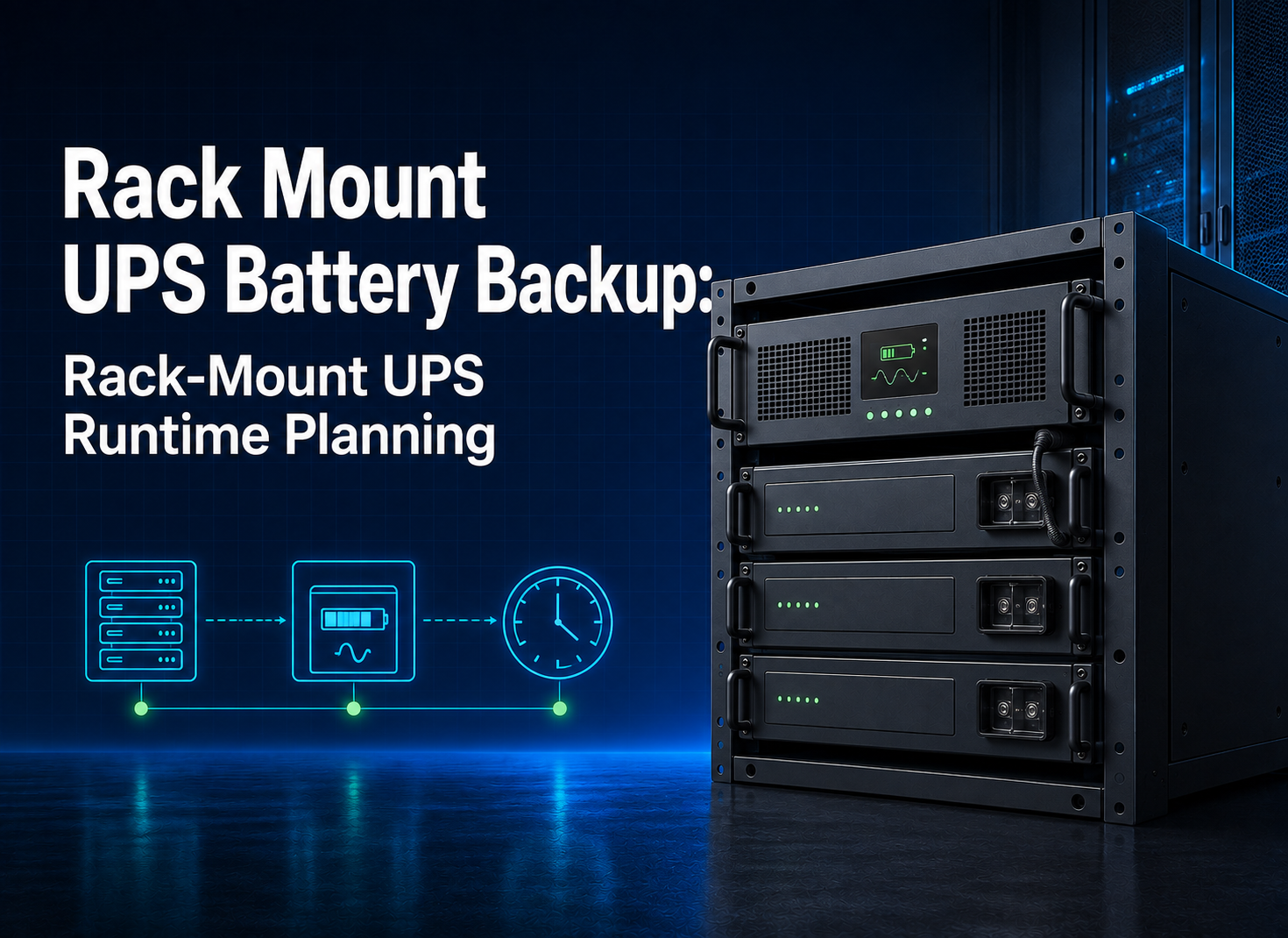
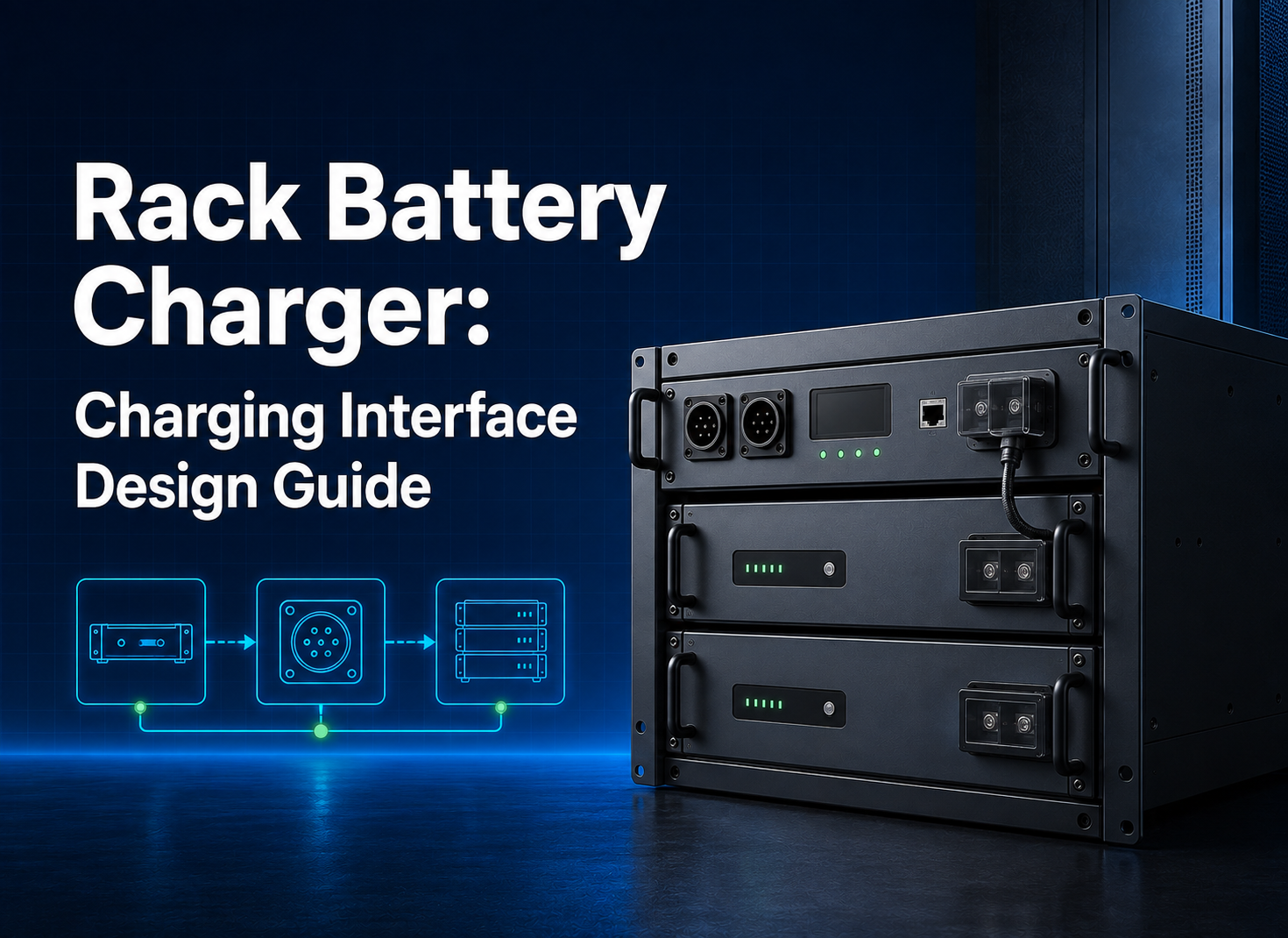
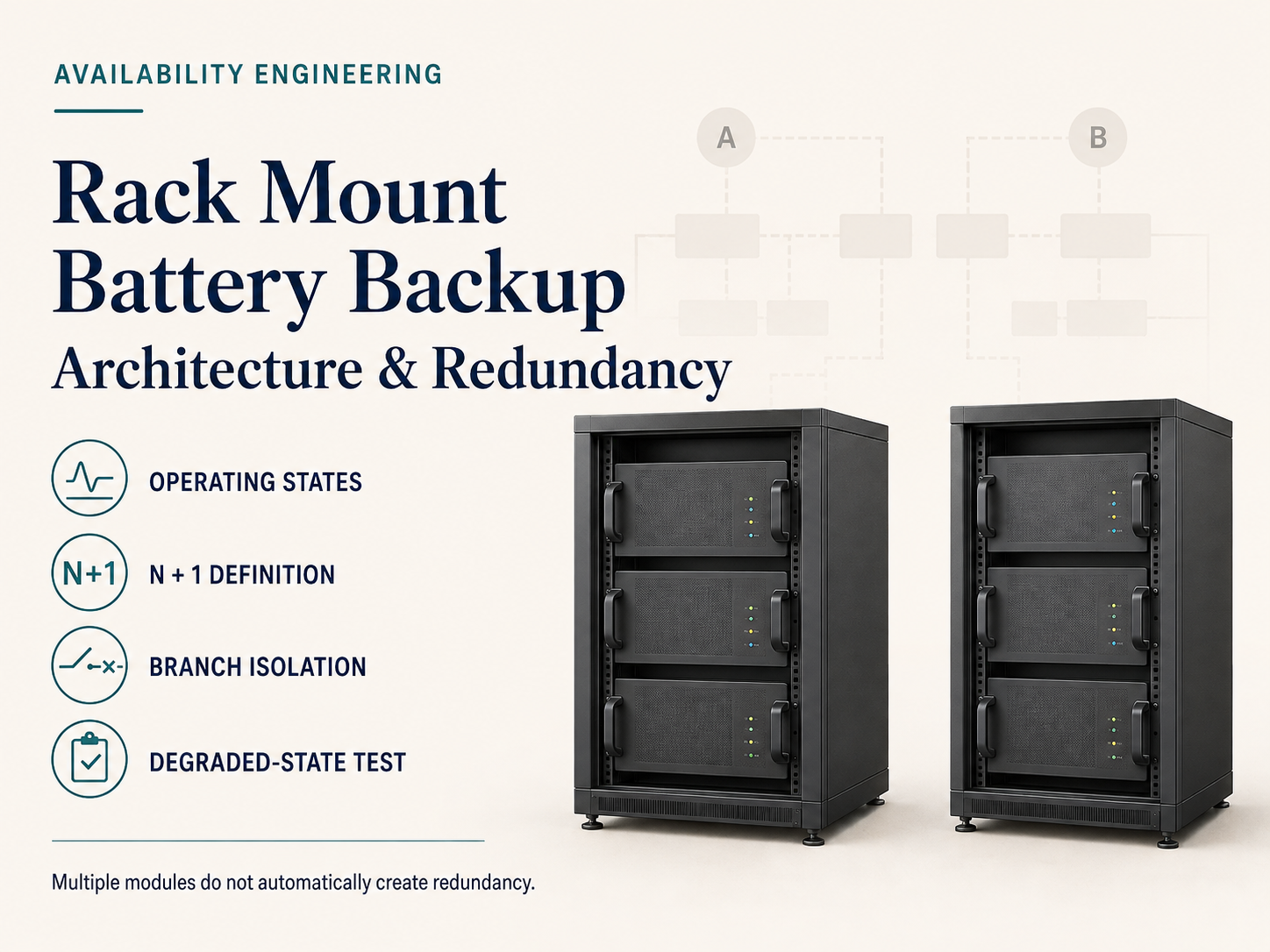
A rack mount battery backup should be designed as a service architecture with explicit redundancy, fault isolation, maintenance bypass, and recovery rules. Runtime is only one part of the decision. Buyers must define which loads remain available after each credible failure, how battery branches and power-conversion equipment are isolated, what “N+1” means at the actual duty, and how the remaining system is tested. A collection of rack batteries is not redundant merely because it contains multiple modules.
Write the availability objective as operating states
Start with named states rather than an uptime adjective. Describe normal operation, utility loss, generator transition if applicable, loss of one battery branch, loss of one conversion module, communication failure, maintenance, emergency shutdown, and restoration. For each state, list the loads served, permitted duration, operator action, and acceptable degradation.
This state table turns “backup” into a requirement that engineering and procurement can test. It also exposes priorities: a site may prefer reduced runtime after a branch loss, or it may require the full runtime with one component unavailable. Those two interpretations produce different capacity and cost.
|
Operating state
|
Required service
|
Design question
|
|
Normal
|
Carry or stand ready for defined load
|
Which components share duty?
|
|
Source outage
|
Support named loads for stated time
|
What is the starting condition and endpoint?
|
|
One branch unavailable
|
Maintain agreed power/runtime
|
Is reserve energy and current truly independent?
|
|
Planned maintenance
|
Preserve required service safely
|
What bypass and isolation path is used?
|
|
Control/link failure
|
Enter a predictable safe state
|
Which device retains authority?
|
Define N, N+1, and reserve without ambiguity
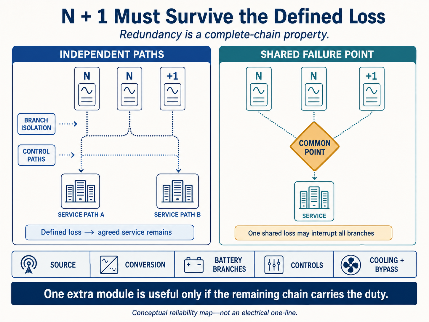
“N” is the minimum equipment needed to deliver the specified service at the stated environmental and operating conditions. “+1” is an additional independent capacity unit or path that allows the service to continue after one defined loss. It is not a spare sitting in storage, and it is not automatically achieved by adding one battery module.
Check redundancy across the complete chain: source, charger/rectifier or inverter/UPS, battery branches, bus, protection, controls, cooling, communications, bypass, and output distribution. Two battery strings connected to one unprotected common point still share a single point of failure. Draw a functional block diagram and mark every component whose loss interrupts the service.
Separate power resilience from energy resilience
Power resilience asks whether the surviving architecture can carry the load immediately after a failure. Energy resilience asks how long it can continue. Calculate both. If one battery branch is isolated, current rises in the remaining branches; verify their time-based limits, conductors, protection, busbars, and thermal conditions at the degraded duty.
For runtime, state the protected load, initial condition, usable-energy definition, conversion losses, reserve, endpoint, temperature, and any aged-life requirement. Do not apply capacity, cycle-life, or derating values from another model. kW and kWh must remain separate throughout the architecture review.
- Evaluate the worst credible component-out condition, not only normal sharing.
- Check load steps and motor or power-supply inrush where applicable.
- Define whether noncritical loads are automatically shed after a fault.
- Reserve enough recharge capability for the required recovery window.
- Document how unequal branch state or age is detected and handled.
Create selective isolation at every battery branch
Each branch should have an identified connection, protection device, isolation method, labeling, and service boundary appropriate to the design. The engineering review should show how a branch fault is cleared, how fault current is limited, and whether healthy branches remain connected. Protective devices must be suitable for the DC duty and coordinated from module to common bus and upstream equipment.
|
Isolation layer
|
Intended function
|
Verification method
|
|
Module/branch protection
|
Clear local overcurrent or fault
|
Coordination basis and controlled test/inspection
|
|
Branch disconnect
|
Create a safe maintenance boundary
|
Operating procedure and absence-of-energy check
|
|
Common-bus isolation
|
Separate battery system from converter/load
|
One-line review and functional exercise
|
|
Emergency action
|
Put the system into the defined emergency state
|
Witnessed response and reset procedure
|
Physical layout should let technicians identify and isolate a branch without reaching across exposed conductors or removing unrelated live equipment. Confirm rack support, restraint, cable routing, touch protection, clearances, lifting, and access. Redundancy that cannot be serviced safely is operationally fragile.
Control current sharing and branch imbalance
Parallel branches require comparable electrical paths and an approved connection topology. Cable length, conductor resistance, connector condition, bus geometry, state of charge, temperature, module age, BMS settings, and contactor behavior can affect sharing. Do not assume currents divide equally because modules have the same label.
Specify how the system detects imbalance and what happens when one branch reaches a limit first. A branch may disconnect, forcing a sudden load step onto the remainder. The control and protection sequence should prevent cascading trips. Expansion and replacement also need rules for firmware, state-of-charge alignment, age mixing, settings, and requalification.
Do not publish or design from an uncertain portfolio-wide parallel count. Obtain the validated limit and topology for the exact battery model, BMS firmware, master/slave logic, communication network, bus, and protection scheme.
Place bypass inside the service strategy
Maintenance bypass allows work on selected equipment while preserving an agreed service path, but it can also remove conditioning or protection functions. Define what remains protected in bypass, how switching is interlocked, whether transfer is permitted under load, and which alarms or operating limits apply. The procedure should identify authorization, prerequisites, sequence, verification, and return to normal.
Bypass is not the same as redundancy. A bypass path may keep loads energized while eliminating battery backup. State this clearly in operating documents so availability reports do not treat “power present” as “backup service available.”
Use product pages only after architecture is frozen
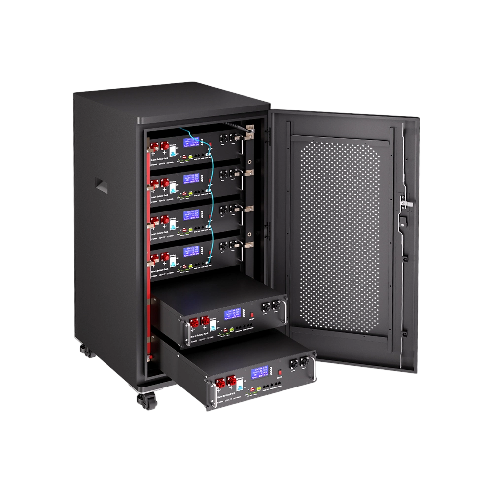
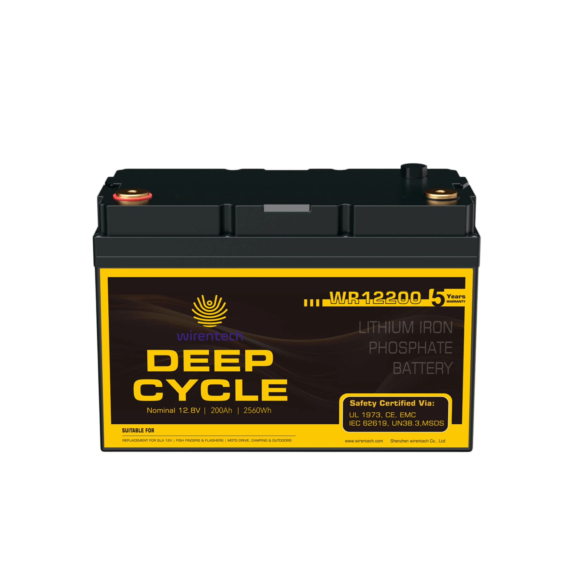
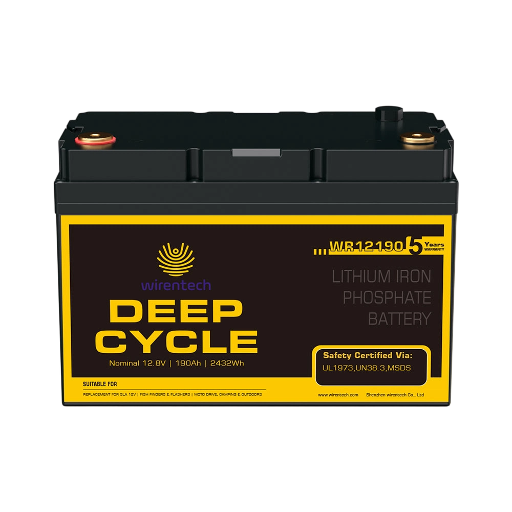
For product screening, buyers can review the 51.2V 200Ah 10kW LiFePO4 Rack Mounted Battery LFP Battery. Its rack-mounted format makes it relevant to a battery-backup shortlist, but the exact product-page name and selling points do not prove runtime, redundancy, continuous output, current sharing, compatibility, expansion limit, certification, warranty, or price.
Request the controlled model documents, drawings, operating limits, BMS/interface files, applicable evidence, and commercial offer. Evaluate the exact product inside the architecture and fault-state table; do not reshape the architecture around an unverified headline specification.

Test graceful degradation instead of normal operation only
Commissioning should establish the baseline configuration and then exercise credible degraded states. Verify exact models, serials, firmware, settings, branch identity, protection, polarity, communications, alarms, monitoring, and initial condition. Use a controlled load and synchronized records so events can be reconstructed.
|
Exercise
|
Expected evidence
|
Unacceptable outcome
|
|
Remove/isolate one branch
|
Remaining system carries agreed service
|
Cascading trip or unknown overload
|
|
Communication interruption
|
Defined fallback or shutdown occurs
|
Uncontrolled charging/discharging
|
|
Transfer/bypass
|
Load behavior matches approved sequence
|
Unexpected interruption or lost protection
|
|
Restore branch
|
Controlled resynchronization and state check
|
Inrush, imbalance, or unapproved auto-rejoin
|
|
Alarm escalation
|
Correct local/remote indication and owner response
|
Missing, ambiguous, or unactionable alarm
|
Retain event logs, measurements, settings, deviations, and closure evidence. A test at commissioning does not remove the need for periodic exercises, especially after firmware updates, replacement, load growth, or topology changes.
Build monitoring around decisions operators must make
Monitoring should answer whether the service is available, which branch is limited or isolated, how much runtime remains under declared assumptions, and what action is required. Define alarm priority, ownership, acknowledgement, escalation, data retention, and loss-of-communications behavior. Avoid a dashboard that reports many values but cannot support a maintenance decision.
Set change-control triggers for added loads, altered runtime, new firmware, replaced modules, changed protection, new inverter/UPS equipment, cooling changes, and expansion. The approved configuration list and state table should be updated before the modified system returns to service.
Compare redundancy proposals on total responsibility
Normalize battery modules, racks, DC distribution, protection, conversion equipment, controls, bypass, monitoring, cooling interfaces, documentation, tests, spares, installation support, commissioning, and service. Require a reliability block diagram or equivalent architecture drawing and a compliance/deviation response. A low price that excludes fault studies, controls integration, or acceptance testing is not comparable.
Commercial claims such as price, MOQ, lead time, production capacity, warranty, and response times must come from the current model-specific offer and contract. Ask who owns configuration changes, remote access, firmware approval, spare readiness, and incident analysis.
Architecture questions for critical-load owners
Does N+1 mean one extra battery module?
Not necessarily. N+1 must be defined against the required service and failure unit. One extra module is useful only if the remaining power, energy, bus, protection, controls, and cooling can deliver the agreed degraded-state duty.
How is rack backup different from a UPS runtime article?
UPS runtime planning focuses on load and autonomy for a UPS interface. This article focuses on system architecture: redundancy, branch isolation, bypass, degraded states, maintenance, and recovery across the full backup chain.
Can all battery branches connect to one common bus?
They can only within an approved design. Review fault current, branch protection, isolation, current sharing, cable symmetry, bus rating, controls, and the effect of losing the common bus.
What should happen when one branch communication link fails?
The expected state must be documented for the exact system—such as a defined limit, controlled isolation, or shutdown—and verified in a test. An interface name alone does not define behavior.
How often should failure and bypass exercises be repeated?
Set intervals from criticality, site rules, equipment instructions, and change history. Repeat after material changes and retain results, deviations, and closure actions so readiness is demonstrated rather than assumed.
What inputs are needed for a redundancy quotation?
Provide the protected-load profile, required runtime, allowed degraded service, failure assumptions, existing UPS/inverter and firmware, architecture drawings, rack/site constraints, communications, compliance market, quantity, and acceptance exercises.

Availability depends on controlled failure behavior
The defensible rack mount battery backup is the architecture that delivers a stated service in normal and defined degraded states, isolates faults selectively, supports safe maintenance, and returns to service through a controlled sequence. The central limitation is that adding modules does not automatically remove shared failure points; the complete electrical and control chain must be reviewed.
For a qualified architecture proposal, send Wirentech the load and runtime requirements, state/failure table, required redundancy, UPS or inverter identifiers, DC window, rack and room constraints, protection concept, communications, destination, quantities, and witness-test expectations. Request an exact-model response that marks every assumption, shared point, and deviation before commercial release.