A powerwall installation should move through five controlled stages: site survey, approved design, equipment and document verification, physical installation, and commissioning with handover. Before work begins, confirm the wall or floor support, clearances, electrical architecture, isolation and protection, inverter and battery compatibility, environmental limits, permit path, emergency access, and installer responsibilities. Do not select equipment from appearance alone. The safest buying decision is the installation package whose assumptions, settings, tests, and service ownership are written down before energization.
Here, “Powerwall” is used as a familiar comparison term for wall-mounted home-storage installations. Wirentech products are independent alternatives; they are not Tesla products, are not affiliated with Tesla, and are not presented as technically or certification-equivalent. The workflow must be applied to the exact selected product and local requirements.
Stage 1: survey the site with the installer present
Record the proposed location, wall or floor construction, dimensions, access path, drainage or water exposure, dust or contamination, ambient conditions, sunlight, ventilation, nearby ignition or heat sources, working space, emergency route, network coverage, and cable path to the electrical point of connection. Photograph and dimension the area; do not approve a location from a marketing image.
Identify the loads to be supported and whether the objective is backup, solar self-consumption, tariff shifting, off-grid operation, or a combination. Collect utility and solar information, main-panel and subpanel ratings, existing inverter or gateway details, generator interactions, and any circuits that must be shed. A qualified project party must confirm the design and local code implications.
|
Survey item
|
Installer records
|
Decision before design
|
|
Structure
|
Substrate, condition, thickness or framing evidence
|
Mounting method and responsible structural approval
|
|
Electrical
|
One-line, panel ratings, earthing/grounding, cable route
|
Architecture, point of connection, protection, isolation
|
|
Environment
|
Temperature, moisture, sunlight, contamination, access
|
Product location and enclosure suitability
|
|
Operations
|
Backup loads, outage mode, generator/PV interaction
|
Control sequence and load-shedding plan
|
Stage 2: turn loads into energy and power requirements
List each protected circuit with running power, starting behavior, expected duration, and priority. Calculate required delivered energy, then include conversion losses and an agreed reserve. Keep nominal battery energy separate from usable energy; the latter depends on the approved operating window and conditions.
Power sizing must cover simultaneous loads and short events. The inverter, battery current limit, conductors, connectors, protection, and thermal environment need the same duty definition. Avoid calling a battery “5 kW” unless the applicable documentation states the type of power, duration, conditions, and system boundary.
Create operating modes. A normal outage mode may support refrigeration, lighting, communications, and selected outlets; a conservation mode may shed discretionary loads; a high-demand mode may be prohibited. The handover should explain those boundaries to the operator.
- Measure or document loads instead of estimating a whole-home label.
- State required backup time and minimum reserve.
- Separate continuous demand from start or surge events.
- Check recharge time from grid, PV, or generator under the intended control logic.
- Tie sizing assumptions to a commissioning demonstration.
Stage 3: approve the electrical and control architecture
The design should show battery, inverter or hybrid inverter, gateway or meter, protected-load panel, isolation, overcurrent protection, emergency shutdown where required, earthing or grounding, communications, and utility, PV, or generator interfaces. Assign design and supply responsibility for every element.
Compatibility is not proven by voltage family or by the presence of CAN or RS485. Obtain a dated validation record for the exact battery, inverter model, firmware, protocol, pinout, wiring, settings, and operating behavior. Where no record exists, require a bench or controlled site test before final release.
Test assumptions for communication loss and equipment faults. Decide whether the inverter follows BMS limits, how alarms are displayed, what causes shutdown, how the system restarts, and what the operator may reset. Preserve approved settings so a later firmware change can be reviewed against the baseline.
Stage 4: verify structure, clearance, and service access
Wall-mounted equipment requires an approved substrate, bracket, fasteners, loaded mass, fastener spacing, and installation method. A finished wall surface does not demonstrate structural capacity. The installer should locate services and hidden hazards, follow the controlled drawing, and record fastener type and installation.
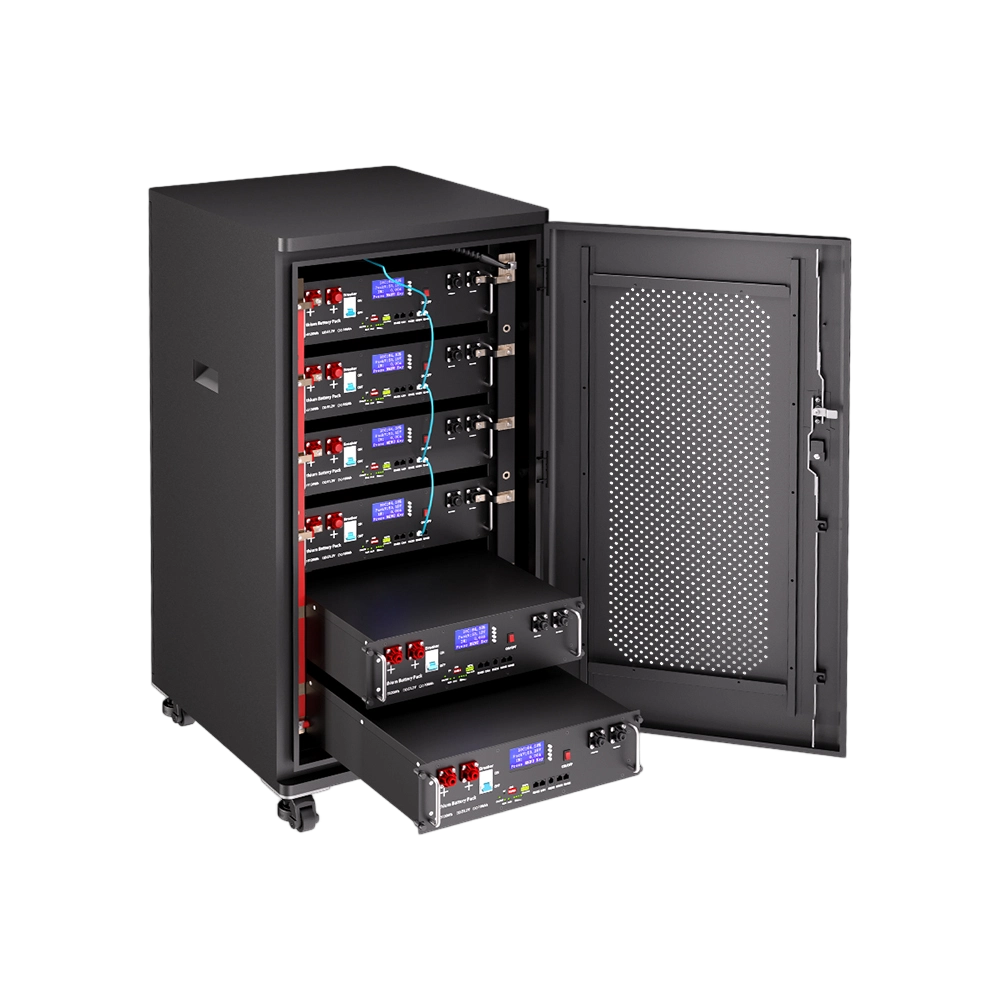
Rack- or floor-mounted alternatives need their own floor-loading, restraint, stability, and access review. Do not use a rack product’s installation method as evidence for a wall-mounted product or vice versa. Product form is a design input, not a permission to improvise mounting.
Maintain clearances required by the product documentation and project rules for ventilation, operation, cable bends, isolation, inspection, and removal. Consider doors, shelves, vehicles, stored materials, flooding paths, and future equipment. The chosen location should allow safe service without dismantling unrelated systems.
|
Physical interface
|
Verify
|
Handover record
|
|
Support
|
Substrate/floor, loaded mass, bracket or restraint
|
Approved detail and installation photos
|
|
Clearance
|
Ventilation, working space, cable bend, removal path
|
Dimensioned as-built location
|
|
Environment
|
Temperature, moisture, sunlight, contamination
|
Allowed conditions and restrictions
|
|
Access
|
Isolation, labels, emergency and service route
|
Operator instructions and contact path
|
Stage 5: compare independent architecture alternatives
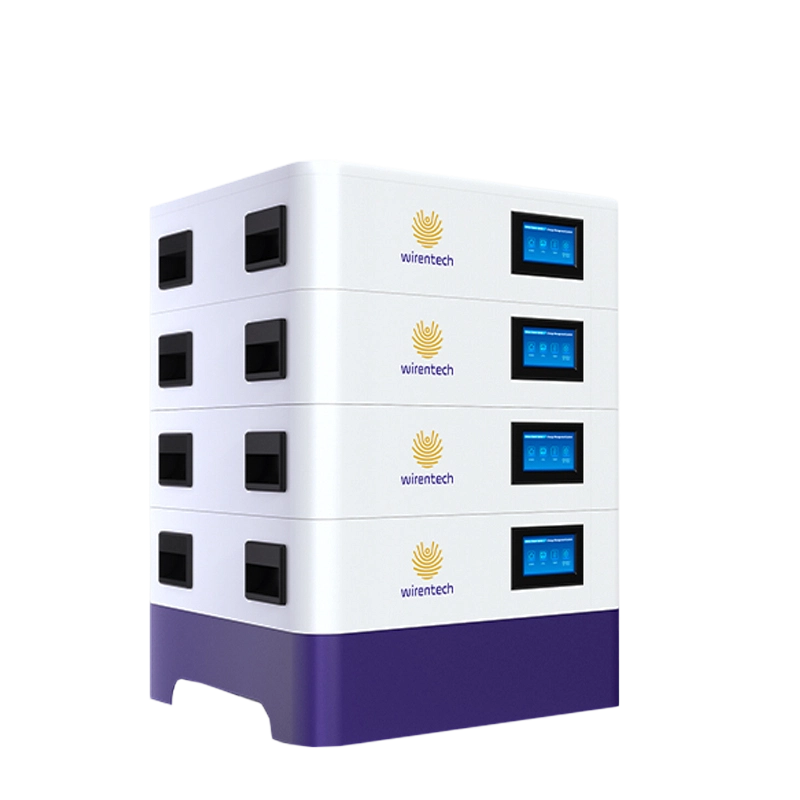
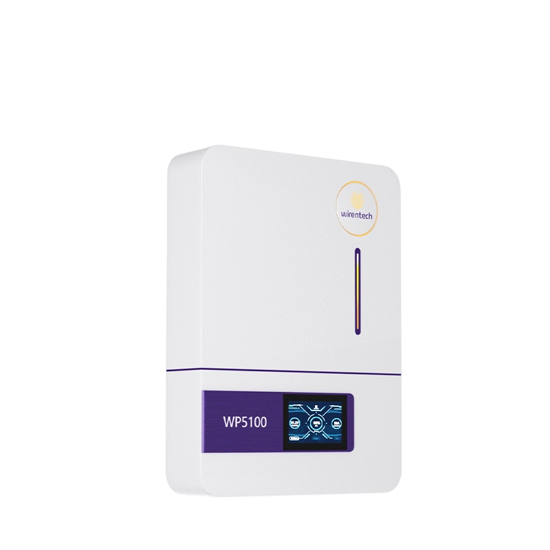
For buyers comparing architectures, the 51.2V 945Ah 48kWh Home Solar Backup Battery provides one independent alternative. The 51.2V 200Ah Stackable LiFePO4 Wall Mounted Battery provides a separate path where wall or stackable form is being screened.
These are independent Wirentech products and have no Tesla affiliation or default equivalence. Their published names and forms help a buyer ask which architecture fits the site; they do not prove usable capacity, continuous output, cycle life, inverter compatibility, permitted parallel quantity, certifications, warranty, price, or installation approval.
Request current model-specific datasheets, drawings, installation instructions, BMS and protocol files, transport and compliance documents, warranty terms, and an integration test plan. Compare only the alternatives that can be checked against the site's architecture and acceptance plan.
Stage 6: review permits, safety evidence, and responsibilities
Identify the authority having jurisdiction, utility or interconnection needs, electrical permit path, fire or building review, installer qualifications, inspection stages, and documentation required in the installation market. Requirements vary; the supplier should not promise universal approval.
Check every certificate or report against exact model and scope. UN 38.3 supports transport review, not installed-system approval. UL 1973 recognized-component language cannot be expanded into a full-system listing. UL 9540A refers to a test method and report context, not a stand-alone product certification. Buyers should request the exact tested configuration and review its laboratory, date, and boundary instead of assuming that another product's report applies.
Document emergency isolation, alarm response, contact information, fire-service or facility procedures as applicable, and who is authorized to service the system. Safety is a shared project process, not a marketing adjective attached to chemistry.
Stage 7: install with controlled checks
Before installation, verify model, serial numbers, shipping condition, documents, drawings, accessories, firmware where visible, and compatibility approval. Confirm the system is isolated and follow the approved sequence. Record mounting or restraint, cable type and size, route, polarity, termination, torque, protection-device details, grounding or bonding, communications, labels, and photographs.
Do not energize to “see if it works” when an interface remains unresolved. Stop for damaged equipment, mismatched model, undocumented firmware, incorrect connector or pinout, missing protection, unsuitable support, or environmental conflict. Resolve the deviation through the responsible designer or supplier and update the as-built record.
Keep battery DC cables as designed and protect them from abrasion, sharp bends, strain, and unapproved sharing with other services. Where several units are allowed, follow the validated busbar, branch protection, addressing, state-of-charge alignment, and current-sharing procedure. Do not apply a parallel limit published for another model or topology.

Control post-installation changes and service events
An installation can drift out of its approved state through firmware updates, inverter replacement, added PV, changed backup loads, new generators, altered tariffs, relocated equipment, network changes, or a battery replacement. The handover pack should define which changes require review and who authorizes them. A service technician should not have to infer the baseline from screenshots or memory.
Maintain a configuration register with battery and inverter models, serial numbers, firmware, protocols, settings, protection devices, drawings, cable and mounting details, commissioning date, test results, and known limitations. After any service event, record the fault, diagnostics, replacement parts, settings, tests, and return-to-service approval. Preserve previous versions so a change can be traced if behavior worsens.
Battery replacement deserves special control. Confirm model revision, state of charge, age-mixing policy, firmware, communications, mechanical fit, and the supplier’s approved procedure before combining a new unit with existing equipment. If the exact replacement is unavailable, do not accept “equivalent” without a documented engineering comparison and retest plan.
Periodic review should confirm physical condition, clearances, labels, connections according to the approved maintenance method, alarm history, firmware status, monitoring, emergency instructions, and operator knowledge. The interval comes from the applicable documentation and project plan; do not invent a universal schedule. When repeated alarms or changes appear, escalate them through the responsible service and engineering route rather than normalizing them.
The service plan should also define data access. Identify which logs the owner can export, how long events are retained, who may change settings, and how remote support is authorized. If a vendor requires cloud or network access, coordinate credentials, user roles, updates, cybersecurity review, and loss-of-connectivity behavior with the owner’s policies.
At the end of each service visit, test the functions affected by the work rather than relying on an “online” indicator. A changed inverter, meter, communication cable, firmware, or battery can alter charge limits, state-of-charge reporting, alarms, and backup behavior. The technician should close the visit with results, unresolved exceptions, and a clear return-to-service approval.
Where the owner plans future load growth, PV expansion, or a second battery, document a review trigger rather than reserving capacity by assumption. Revisit usable energy, continuous and transient power, recharge window, inverter limits, switchboard capacity, protection, communications, structural support, clearances, evidence, and permit implications. Expansion is a new design decision tied to the installed baseline.
Keep an operator-facing change log alongside the technical register. It should state what the user will notice after an update: revised backup circuits, different reserve behavior, new alarm handling, changed monitoring, or altered restart steps. Clear operational communication prevents a technically valid modification from creating unsafe expectations during an outage.
Stage 8: commission normal, fault, and recovery behavior
Commissioning proves that the installed configuration behaves as designed. Verify polarity, voltage, insulation where applicable, protection settings, isolation, communications, inverter settings, meter direction, firmware versions, state-of-charge reporting, alarms, and emergency functions before representative operation.
Run a controlled charge and discharge sequence. Demonstrate protected-load operation, load shedding, PV or grid charging as applicable, transition behavior, communication-loss response, shutdown, restart, and recovery after an alarm. Observe temperature and cable or termination behavior within the approved test method. Save logs and measurements.
|
Commissioning test
|
Pass criterion basis
|
Record
|
|
Configuration
|
Approved models, firmware, wiring, settings
|
Version and settings sheet
|
|
Functional operation
|
Contracted normal and backup modes
|
Time-stamped test log
|
|
Protection/alarm
|
Approved trigger and response
|
Event record and reset method
|
|
Communication loss
|
Defined safe fallback and recovery
|
Observed behavior and owner sign-off
|
|
Handover
|
Operator can isolate, monitor, and escalate
|
Training and document receipt
|
Any exception should have an owner, risk decision, correction, and retest. A workaround that is not included in the approved as-built baseline should not disappear into an installer note.
Stage 9: hand over an operable system
The owner should receive as-built drawings, product and installation manuals, model and serial register, settings and firmware record, test results, applicable certificates or reports, shutdown and restart instructions, maintenance plan, alarm guide, support contacts, warranty terms, spare or replacement process, and change-control rule.
Explain operating limits in plain language. Which loads are protected? How long was the system demonstrated under the acceptance conditions? What must be shed? How is the reserve managed? What happens after an outage or protective shutdown? Which actions require a qualified technician?
Warranty, cycle life, MOQ, lead time, and price must come from current model- and market-specific documents or quotations. Do not accept a universal promise without those records. Record the contract version and claim route rather than repeating a headline duration.
Frequently asked questions for installation planning
Who should perform a powerwall installation?
Use qualified parties required by the installation market and project scope. Structural, electrical, utility, fire, and commissioning responsibilities may involve different professionals or authorities.
Can the battery be mounted on any wall?
No. Verify loaded mass, substrate, bracket, fasteners, hidden services, clearances, environment, and the product’s controlled installation instructions. Obtain structural approval where required.
Does the word Powerwall mean the linked products are Tesla products?
No. The linked Wirentech products are independent alternatives used for comparison. There is no Tesla affiliation, equivalence, or certification parity.
How is inverter compatibility confirmed?
By exact battery and inverter models, firmware, protocol, pinout, wiring, settings, validation date, and observed behavior. An interface name alone is not proof.
How should installation cost be compared?
Normalize battery, inverter or gateway, electrical work, mounting, protection, permits, logistics, commissioning, monitoring, training, service, exclusions, delivery basis, currency, and quotation validity. Do not use a universal price per kWh.
Which documents should arrive before installation?
Request current datasheet, drawings, manuals, protocol and compatibility record, transport and applicable compliance files, labels, warranty terms, and approved design and commissioning procedures.
Can more batteries be added later?
Only within the exact product’s validated expansion rules. Confirm model, age-mixing policy, firmware, topology, protection, communications, space, structural capacity, and retest requirements before promising expansion.
What should the owner test at handover?
Witness the contracted operating modes, monitoring, alarms, isolation, shutdown, restart, communication-loss behavior, representative backup loads, and document/training delivery.
Installation judgment: close every interface before energization
The quality of a powerwall installation is visible in its decision trail: surveyed conditions, approved architecture, model-specific compatibility, structural and electrical records, permit and evidence review, controlled installation, witnessed commissioning, and usable handover. A clean-looking wall does not compensate for an undefined control or protection interface.
Send Wirentech and the installer the site photographs and dimensions, support details, protected-load schedule, required runtime, inverter and firmware, one-line information, PV or generator context, communications, installation market, environmental conditions, project quantity, required documents, and acceptance tests. Ask both parties to return responsibilities and exceptions before equipment is ordered.