

Nov. 06, 2026
The modules operate at a common nominal DC voltage, and their available capacity can add, but each module carries current through its own path to the common feed. That is the essential difference from placing modules in series, which raises voltage. Parallel connection creates several current sources feeding one bus; it does not make their individual BMS limits, cable resistance or states of charge disappear. Victron's battery-bank wiring guide illustrates these electrical distinctions.
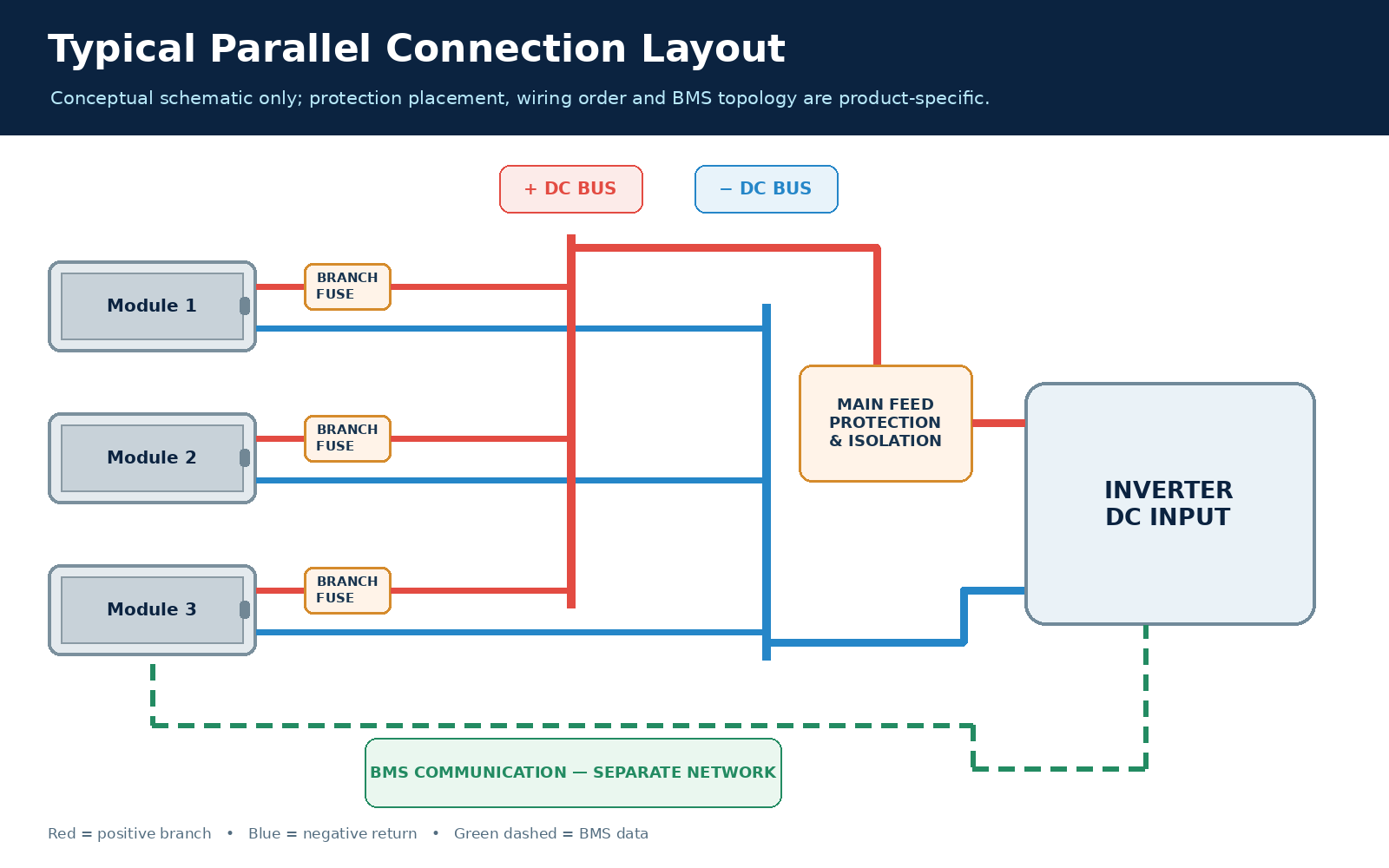
Picture two approved modules with their positive branches joining a positive bus and their negative branches joining a negative bus. The common feed takes power from those buses to the inverter. Each module sees approximately the same bus voltage, yet the current from each is set by its own voltage, internal behavior and total path resistance. The total current available to the load is bounded by what the modules can deliver and what the bus, feed, protection and inverter can carry. Adding a second module does not double a limiting inverter input rating or make an undersized common conductor acceptable.
Each module therefore needs an inspectable path to the bus and back. A shorter path or a BMS restriction can shift current among branches even when module labels match.
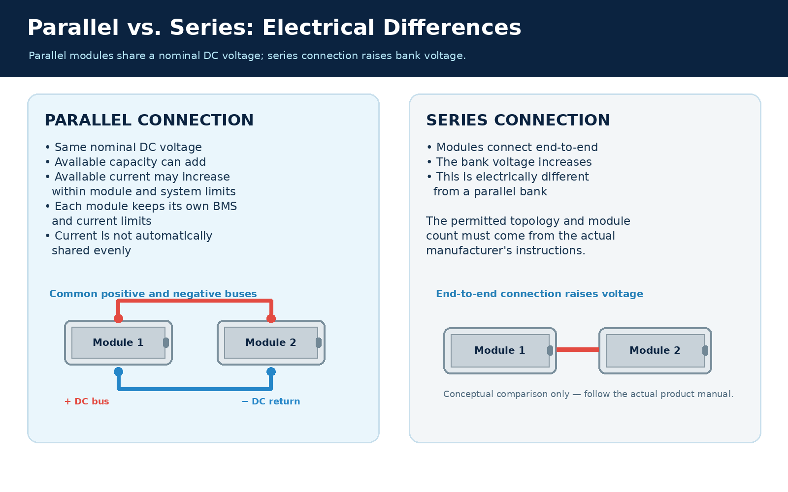
Only modules and configurations supported together by the actual manufacturer's instructions should be paralleled, and a new branch should meet the documented starting voltage or state-of-charge condition before it is closed. The same nominal voltage printed on two cases does not prove that their BMS firmware, allowed parallel count, communication settings, limits or terminal arrangements are interchangeable.
Before connecting a new set, identify the exact model and applicable manual for each module, the supported number of parallel units and the required system mode. Check for active faults and for the specified initial voltage or state-of-charge relationship. A significant voltage difference can produce an uncontrolled equalizing current when the branches are joined, even before the intended load operates. The correct permissible difference must come from the applicable instructions; inventing a universal threshold from nominal voltage would conceal a real hazard. EG4's LifePower4 paralleling guide is an example of a manufacturer documenting model-specific connections and starting conditions, not a universal instruction for another brand.
Polarity must be unambiguous at both module and bus ends. A visually similar connector or cable color cannot substitute for identifying positive and negative terminals and checking the resulting circuit while it remains isolated. Also establish that the terminals, branch conductors, disconnects and common feed are rated for their respective currents. Physical rack fit alone is not electrical compatibility. Conversely, a product page stating that parallel connection is possible does not by itself define a complete approved wiring and control configuration.
Current sharing depends on each module's complete loop through its positive connection, common load path and negative return. A lower-resistance loop tends to carry more current, so comparing only the positive lead lengths misses half the circuit. Terminal contact, connector quality, conductor size and route length can all change the loop resistance.
Take a hypothetical two-module daisy chain in which the load's positive and negative leads attach beside the first module. Current from the second module travels through additional inter-module connections in both directions. The first module has a shorter path to the common feed, and under load it can supply more current. The resulting difference is not a mysterious battery property; it follows from the different voltage drops in the loops. Victron's parallel bank wiring examples show why end takeoff and connection arrangement matter.
Path symmetry can be improved by taking the positive feed from one end of a permitted chain and the negative return from the opposite end, or by giving each module independent positive and negative branches to rated busbars. Neither drawing guarantees equal current in the field. Internal module resistance, state of charge, BMS behavior and connection contact remain part of the effective path. Equal cable lengths are useful only when cable type, cross-section, terminations and the full return path are also considered.
Test current and voltage drop in each branch under the same representative load. A high-current branch may have a lower-resistance route; a low-current branch may be restricted or at a different state. Light-load measurements can miss differences that grow with current. The goal is to keep each branch inside its rating and understand any imbalance, not to demand mathematical equality.
Independent positive and negative branches to appropriately rated busbars are often the clearest layout when several modules need inspectable paths and separate protection. A manufacturer-permitted diagonal takeoff can also reduce end-to-end path differences in a simpler chain. Same-end daisy-chain takeoff is a poor default when it gives the near module a systematically shorter complete loop.
The choices can be compared under the same number of modules, conductor type and load. This table names the entire out-and-back path because that is what controls voltage drop and current division; it does not assign a numerical sharing claim to an unmeasured installation.
| Layout | Complete positive-and-negative path | When defensible | Failure mode and verification |
|---|---|---|---|
| Same-end daisy-chain takeoff | Near module traverses fewer inter-module sections in the complete loop | Mainly a counterexample for evaluating an existing layout; use only if the actual instructions and measured behavior support it | Near branch can carry more current; measure each branch under load and examine connection drops |
| Diagonal takeoff | Positive and negative feeds are taken from opposite ends of a permitted chain | A simpler approved arrangement when each full loop can be made reasonably symmetric | Internal differences and joints remain; measure sharing and verify every branch remains within limits |
| Independent branches to busbars | Each module has its own positive and negative route to common rated buses | Useful when separate branch protection and accessible inspection are needed | Unequal branch construction or an undersized bus can defeat the benefit; compare branch length, terminations, ratings and loaded currents |
Busbars make branch boundaries explicit, but their ratings and the main feed must cover the combined current. They also add joints whose quality matters. A diagonal chain may use fewer common parts yet still needs the manufacturer's permitted topology and a way to isolate faults. These are layout decisions, not a claim that one geometry fixes a module whose BMS is limiting or whose state differs from its peers. Where the maker prescribes a specific connection pattern, that instruction takes precedence over a generic diagram.
Protect each branch and the common feed according to the fault current and conductor path they can experience, using the devices and locations required by the approved design and module instructions. A fault in one branch is not the same electrical event as a fault on the common feed: other modules can contribute current into the affected path, while the common feed carries the combined bank current during normal operation.
With separate branches, appropriate branch protection and a suitable disconnect can allow one module path to be isolated without assuming that a single main device protects every smaller conductor equally. The main feed needs protection and isolation appropriate to its aggregate current and cable. If the bus or distribution hardware is enclosed, access and safe isolation also affect how a fault can be investigated. Victron's Lithium NG installation documentation treats battery cabling and protection as part of the actual system installation; its device choices are not a transferable specification for another module.
The protective path must be understood in both directions where current can flow. A short on one module branch might be fed by the other parallel modules through the common bus. A fault on the main feed can draw from the entire bank. A device sized only by a module's normal discharge rating might still have the wrong DC interrupting capability or coordination for a prospective fault. Those decisions require the actual battery, conductor, bus and protective-device data. The present connection task needs their locations and roles made explicit; it does not replace a full protection-device selection and coordination design.
A module's internal BMS does not replace protection for external wiring and currents supplied by other modules. Before energizing, trace each protected branch from positive terminal through the bus and back to negative. Revise a layout with an unprotected section even if open-circuit voltage looks correct.
The DC cables carry charge and discharge current; BMS communication identifies modules and exchanges status or allowable operating limits. A bank can be physically paralleled on the DC side while its inverter or master module still sees the wrong number of modules, stale limits or no valid control data. Power continuity alone is not proof that the parallel system is coordinated.
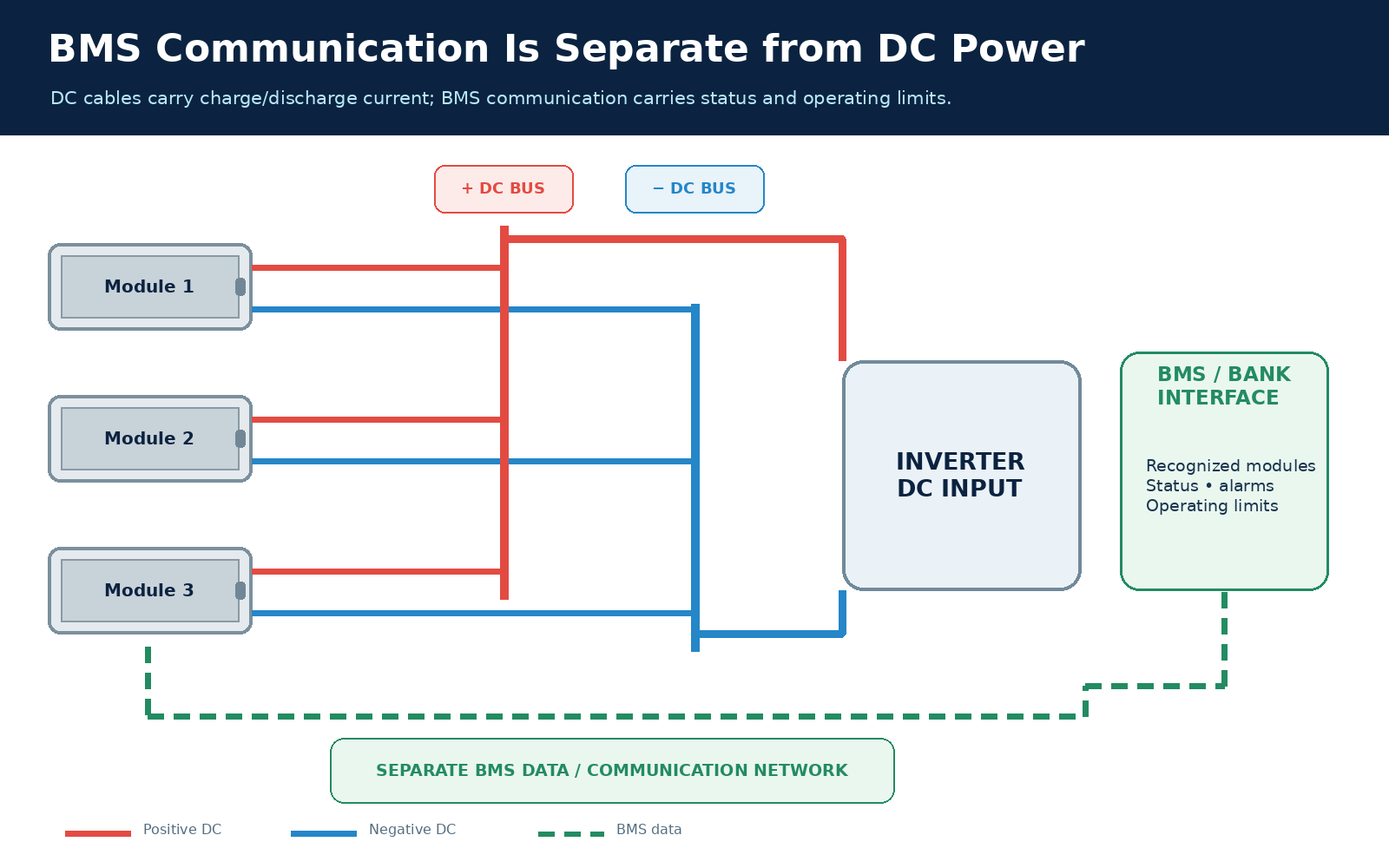
Many rack systems use a module-to-module data chain and a defined connection from a master or bank interface to an inverter. The actual connector, cable, address and termination depend on the product. EG4's paralleling guide illustrates that DC connections and communications have separate arrangements. Its port labels and version rules should not be copied onto a different product. A generic diagram can show two networks, but a real installation needs the matching manual.
The distinction matters during both normal operation and a fault. If one module disconnects, the remaining modules may carry more DC current; in a communicating design, check whether the controller's view of the bank's operating limits has changed accordingly. If communication fails while DC cables remain intact, the inverter might enter a different mode, restrict output or stop according to its configured behavior. That behavior belongs to the specific inverter–battery pairing, not to the mere existence of a CAN or RS485 socket. The correct commissioning question is whether the intended number of modules and their limits are actually recognized, and whether a communication alarm produces the expected controlled response.
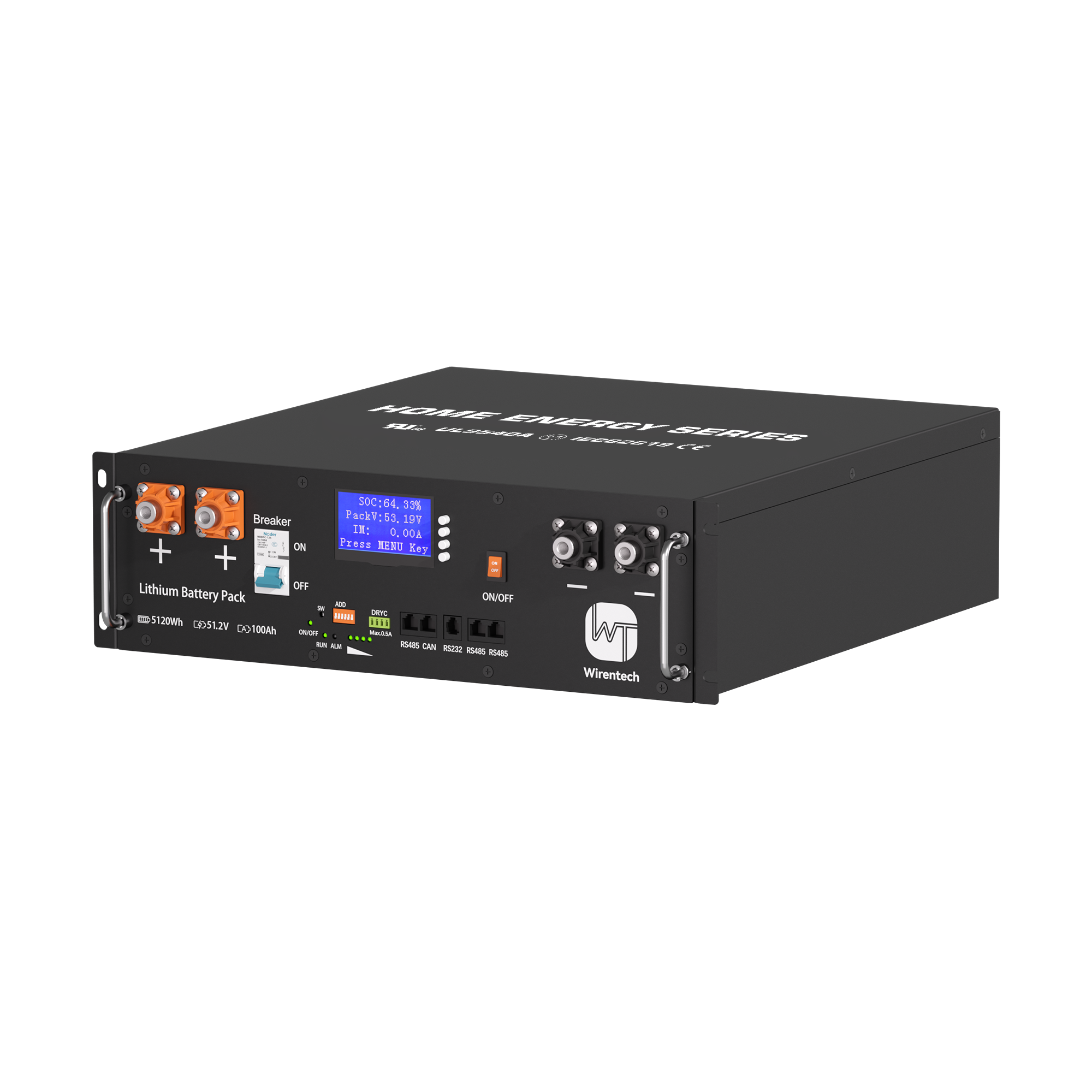
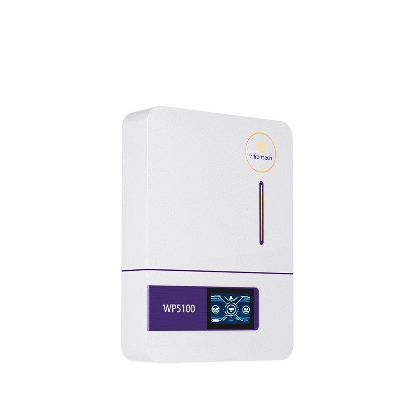
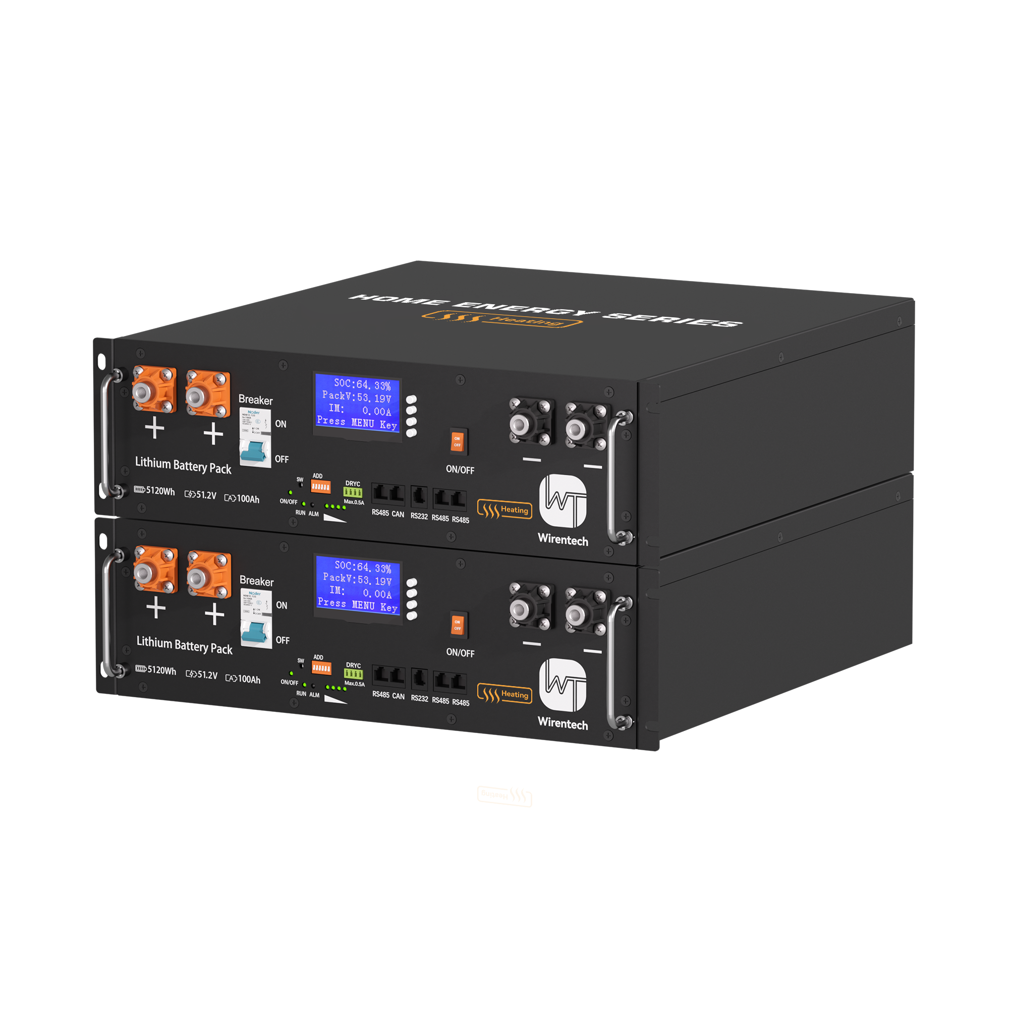
The Wirentech WT5100 product page can be used to view its published interfaces and product details. It does not establish that a selected inverter's protocol, firmware or addressing arrangement will work with this bank. That conclusion would need matching documentation for the exact pairing.
Start with isolated modules that meet the approved connection conditions, establish and inspect the DC and data paths, energize in the documented order, then test a representative load while comparing branch currents and alarms. Each transition needs a visible pass condition. The sequence is a method for verifying a new parallel connection, not a substitute for model-specific torque, switching or safety instructions.
With sources isolated, identify the modules, allowed parallel quantity and starting states established earlier. Confirm the planned positive and negative routes against the drawing, the location of branch and main protection, and the intended BMS network. Check polarity at the point where each branch will join the buses. A branch with an unexplained voltage difference or active fault should remain disconnected while the condition is resolved. This avoids using an energized bus as a diagnostic instrument.
Complete the physical connections in the manufacturer's required order and inspect the static result before applying the representative load. Each module should have a traceable complete DC loop; no branch conductor should bypass its intended isolation or protection. The communication chain should match the model's specified ports, addresses and termination. A continuity or voltage indication alone cannot show that all BMS messages are correct, so include the controller's displayed module count or equivalent recognition in the next state.
Energize in the actual documented sequence and watch for fault indications. Confirm that the inverter or bank controller recognizes the intended modules and reports the appropriate operating state. An unexpected module count, communication alarm, reversed-polarity indication or immediate trip is a stop condition: isolate according to the instructions and investigate that state before increasing load. Avoid repeated resets that erase the useful fault observation without fixing the connection.
Apply a representative sustained load and any permitted transient test, then record each branch current, bus voltage and relevant module alarms at the same operating moment. Compare branch behavior against the module limits and against the intended path symmetry. The output of the test is not simply “the load stayed on.” It is evidence that the bank's DC branches, main feed and data coordination behave as expected at a meaningful demand. If charging is part of first operation, observe an appropriate charge state as well, because current can distribute differently when its direction reverses. These measurements should be made by qualified personnel using suitable DC-rated instruments and the approved safe procedure; the criterion is observable correct behavior, not an invented universal imbalance percentage.
Unequal measured currents are a diagnostic clue, not immediate proof that one battery is defective. Compare the complete branch paths, contact quality and module states under the same load before deciding whether the difference is acceptable or needs correction. A branch may be carrying less because its path drops more voltage, its BMS is limiting, or it entered the test at a different state.
Measure currents at the same time and load point, and compare voltages at the buses and module terminals where the approved procedure permits. A large difference in drop along one branch points toward its conductors or joints. A normal-looking external path with a module warning points instead toward the module's operating condition or control limit. If the currents change markedly as load rises, resistive path differences become more consequential. If they change after one BMS event, investigate that event before altering cable geometry.
The immediate response is to stop a test that exceeds a module, conductor or system limit, correct the identified cause and repeat the same comparison. A small difference without a breached limit may be normal, but its acceptance must come from the actual product instructions and the bank's duty, not a universal percentage invented for all rack batteries. The first test establishes a baseline for this new installation.
The connection is complete when both networks and all current paths have passed the intended first-operation checks. The physical arrangement explains why sharing should be reasonable; the measured branch response confirms whether that expectation holds in this installation.
Related News

Nov. 07, 2026
Can a Home Battery Start and Run High-Surge Household Loads?
Learn why battery kWh alone cannot prove motor-start backup. Compare inverter surge duration, running demand, simultaneous loads and a supervised backup test.
Nov. 07, 2026
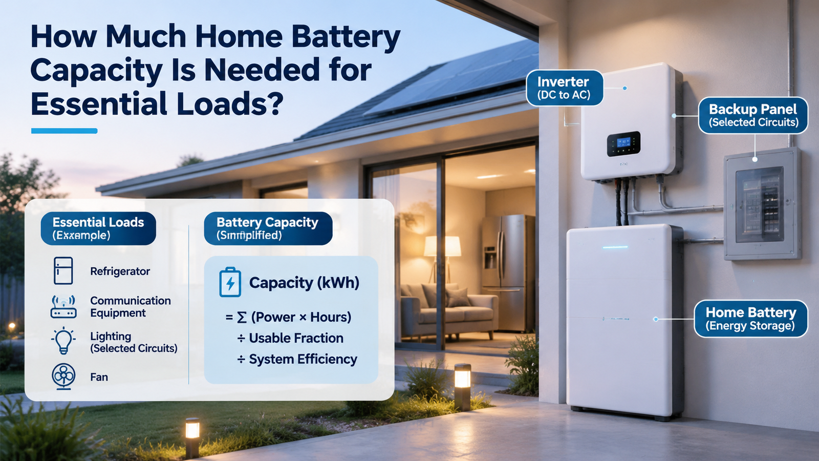
How Much Home Battery Capacity Is Needed for Essential Loads?
Calculate home battery capacity from essential-load power, duty cycle and outage hours. See a transparent kWh example and avoid double-counting losses.

Nov. 07, 2026
How Should a Home Battery Specification Sheet Be Read for Backup and Daily Use?
Compare home battery capacity, usable energy, continuous and peak output, charging limits and rating conditions before judging daily use or backup claims.

Nov. 06, 2026
Whole-Home Battery Backup or Critical-Load Backup: Which Scope Fits the Home?
Compare whole-home and critical-load battery backup by protected circuits, peak power, outage duration and load control to choose a realistic home backup scope.
Nov. 06, 2026
Can a Home Battery Provide Backup Power Without Solar Panels?
A home battery can provide backup without solar if grid charging, outage isolation and backup circuits are configured. Learn what limits runtime and recharge.

Nov. 06, 2026
How Does a Home Battery Storage System Work for a Household?
Follow the energy path through a home battery, inverter and controls. Learn how charging, daily discharge and outage backup differ before comparing systems.

Nov. 06, 2026
How Can A Weak Battery Be Distinguished From A Weak Golf Cart Battery Bank?
Compare like-conditioned unit and bank readings to separate one weak battery from broad bank loss, charging shortfall or connection trouble.
Nov. 06, 2026
How Should A Replacement Golf Cart Battery Bank Be Planned?
Decide whether one unit or the bank needs replacement, then specify voltage, fit, connections and first-charge checks before ordering.

Nov. 06, 2026
What Changes When A Golf Cart Battery Bank Is Converted To Lithium?
Map the battery bank, tray, charger, controller, gauge and accessory interfaces that change when converting a lead-acid golf cart to lithium.

Nov. 06, 2026
When Does Lithium Make Sense Instead Of Lead Acid For A Golf Cart?
Compare lithium and lead acid for the same golf-cart duty, charging routine, maintenance capacity and ownership horizon before deciding whether a switch is worthwhile.

Nov. 06, 2026
How Can Peak Current Demand Be Matched To A Golf Cart Battery?
Compare a golf cart’s acceleration and hill-load current by duration with battery continuous, pulse and protection ratings under matching conditions.