

Nov. 06, 2026
Size the bank twice: first for the energy the load consumes over its required runtime, then for the continuous and short-duration current the battery must supply. Round each result up to a whole, approved module count and use the larger number. A bank with enough nominal kilowatt-hours can still shut down on a peak; a bank that handles the peak can still run out of usable energy before the target time. The result remains preliminary until its DC voltage range, operating window, parallel limit, charging window and actual load behavior have been checked together.
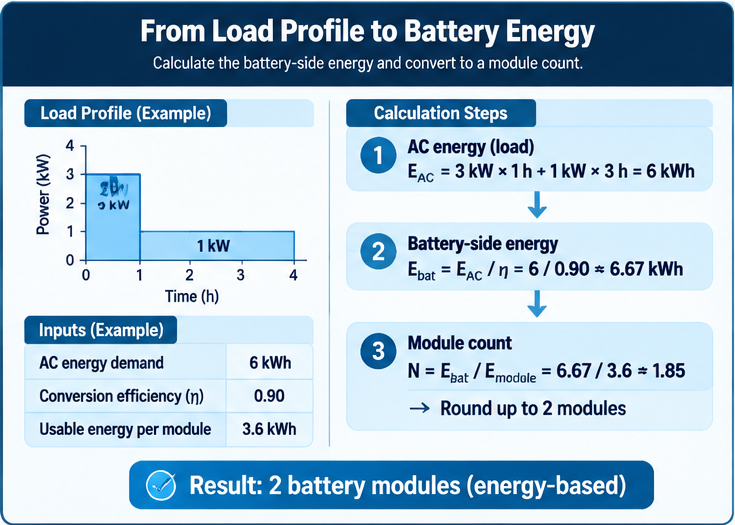
It must deliver enough energy across the entire event and enough current at every relevant instant. Energy is the area beneath a power-versus-time curve, expressed in kilowatt-hours; power is the curve's height at a particular moment, expressed in kilowatts. Two loads can consume the same energy but place very different current demands on a battery bank.
Imagine a hypothetical constant 2 kW load for four hours and a 4 kW load for two hours. Both consume 8 kWh before conversion losses, yet the second requires roughly twice the instantaneous DC current at the same battery voltage. A short startup pulse can make the distinction sharper: it contributes little to total energy, but may determine whether the inverter, conductors, protection and module BMS stay within their timed limits. The DC current relationship follows power divided by voltage, with conversion loss included when an AC load is supplied through an inverter; Victron's electrical theory guide describes these underlying power and voltage relationships.
Define the load boundary: AC output demand needs inverter loss included, while demand already measured at battery terminals does not. Record the duration of each operating state, including relevant startup peaks, instead of sizing from a nameplate maximum alone.
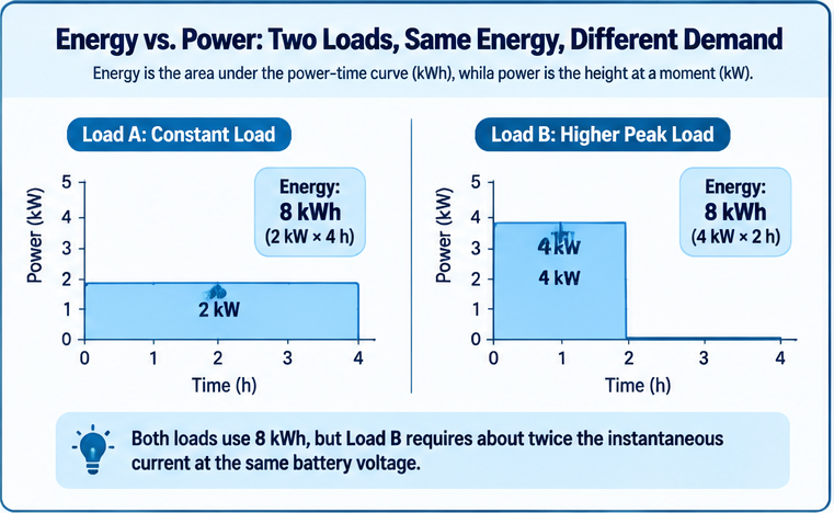
Add the energy of each load interval, translate that requirement to the battery side, and divide by the energy one module can actually deliver within the chosen operating window. For a stepped profile, load energy is the sum of each power level multiplied by its hours. For a continuously varying profile, it is the area under the measured power curve.
Suppose a hypothetical load draws 3 kW for the first hour and 1 kW for the next three hours. Its AC energy demand is 6 kWh: 3 × 1 plus 1 × 3. If a justified design estimate for the combined conversion efficiency over those states is 0.90, battery-side delivery is about 6 / 0.90, or 6.67 kWh. That 0.90 is an illustration, not an efficiency claim for a particular inverter or a universal value. If efficiency changes substantially with power, calculate each interval using the appropriate efficiency rather than applying one convenient figure to the whole event.
Next define energy usable per module. A simple planning form is the module's nominal energy multiplied by the permitted fraction of its state-of-charge window, with any supported correction for the expected temperature, current and aging condition. This is a model, not permission to invent those correction factors. Manufacturer operating limits, inverter cutoff behavior and the required end-of-event reserve determine the actual window. Dividing battery-side energy need by usable module energy gives the energy-based count; round up because a fraction of a rack module is not an installed module.
If the illustrative 6.67 kWh requirement is paired with an assumed 3.6 kWh usable per module, the arithmetic rounds 1.85 up to two modules; an actual design needs a supported usable-energy figure. Additional load duration belongs in the demand profile; an intentionally retained state-of-charge reserve reduces usable energy per module. Do not count the same reserve twice.
Cable and connection resistance produce DC voltage drop and heat, particularly at high current, as Victron's wiring theory explains. Keep losses at their actual boundary so they are neither omitted nor counted twice.
Nominal kilowatt-hours describe a rated battery quantity under specified conditions; delivered kilowatt-hours depend on the permitted discharge window and on what reaches the load after electrical losses. A nominal module value belongs at the battery, while a promised AC runtime belongs at the output. They are different measurement points.
A rack battery may reach the inverter's low-voltage cutoff before every nominal watt-hour is extracted. A BMS limit, high discharge current, low temperature or retained reserve can narrow the usable window. Treating all of these as one generic percentage can conceal a missing constraint.
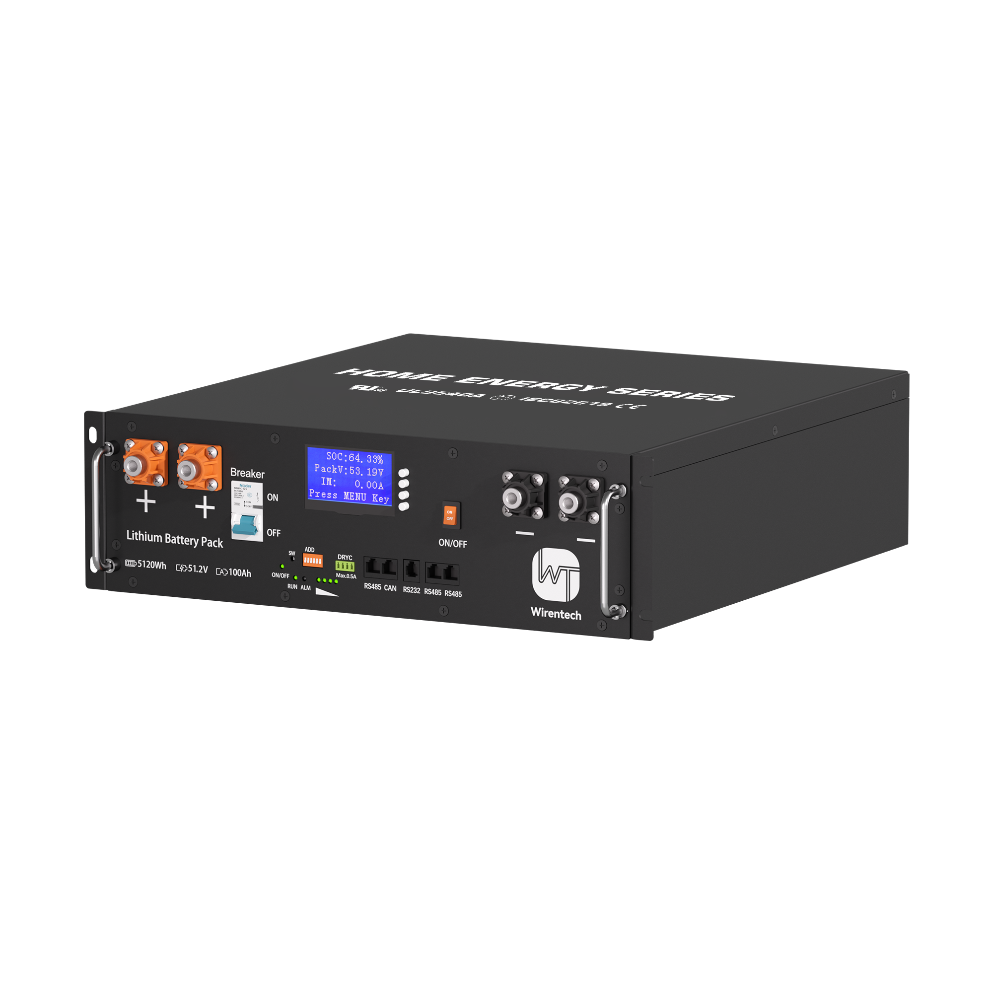
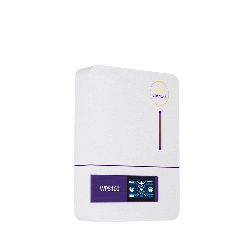
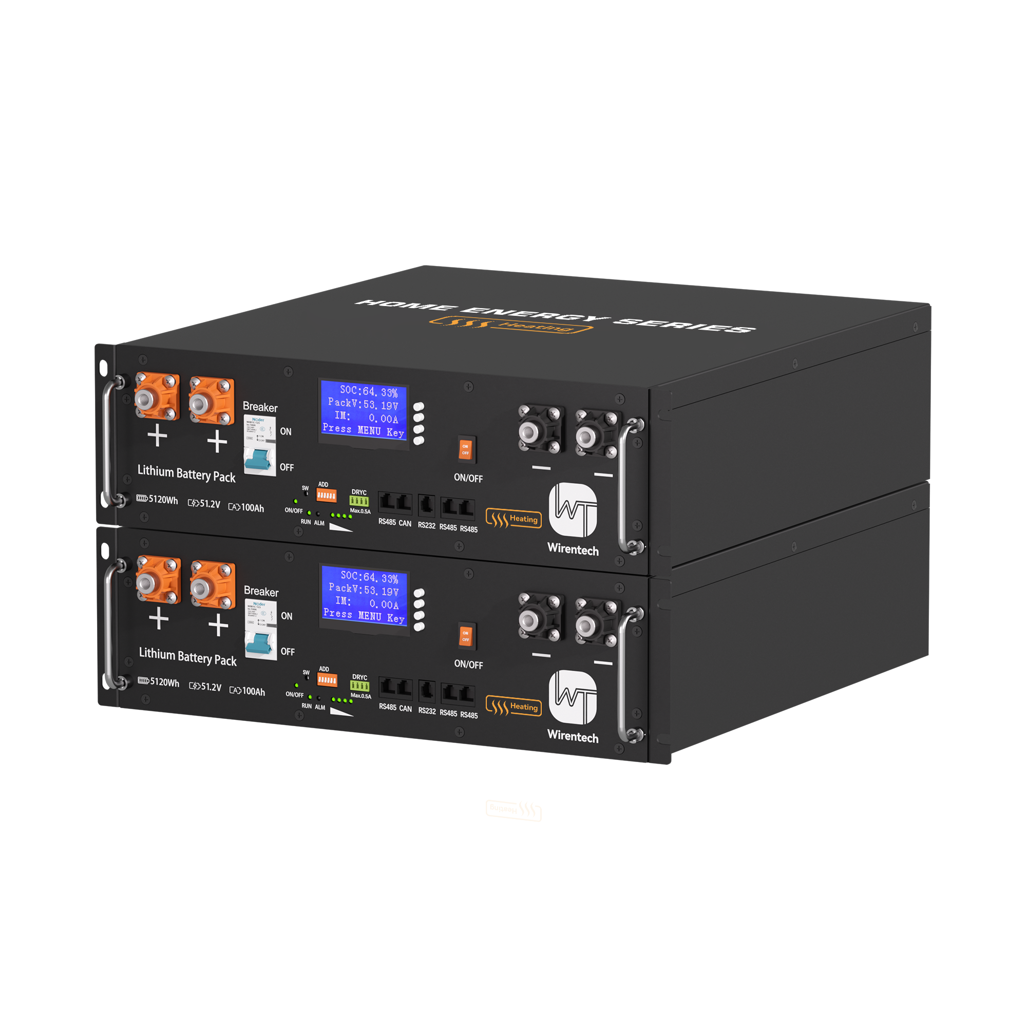
For a concrete product reference, the Wirentech WT5100 module page publishes the module's stated specifications. Its nominal values cannot supply the usable-energy denominator for a different operating window. If that denominator is not yet supported, keep the module count symbolic rather than presenting a runtime guarantee.
Calculate battery-side current at the lowest voltage relevant to the permitted discharge range, compare continuous demand with a continuous module rating, and compare each peak with a rating for the same duration. Round each current-based ratio upward. The larger result sets the current lower bound, subject also to the limits of the common bus, inverter and protective system.
For a DC load, current is approximately power divided by battery voltage. For an AC load through an inverter, estimate battery input power from AC output power and the inverter efficiency at that operating point, then divide by DC voltage. A hypothetical 4 kW AC load at 90% conversion efficiency asks the DC side for about 4.44 kW. At 50 V it implies about 89 A; at 44 V it implies about 101 A before any additional distribution effect. Those voltages and efficiency are illustrative, not a specification for WT5100 or any other product. Their role is to show why the worst relevant voltage, not the most attractive nominal voltage, controls a high-power check.
Now compare that required current with a module's documented allowable discharge current over the needed time. If the allowable continuous current were hypothetically 60 A per module, 101 / 60 would require at least two modules for the continuous state. Yet two parallel modules do not necessarily carry exactly half of 101 A. Different branch resistance, module state or control limits can make one work harder. The count is therefore an initial electrical lower bound, followed by a path and sharing check. Victron's battery-bank wiring guide explains why parallel paths affect current sharing.
A startup or transfer peak needs its own comparison. If the load reaches 7 kW for several seconds, use an inverter and battery rating that explicitly covers that duration. A millisecond surge label does not establish a several-second capability; a continuous label may be conservative but still needs the actual transient checked. If no matched timed rating is available, the peak constraint is unresolved. Reducing the peak, staging starts or choosing an appropriately rated system may be more sensible than assuming that extra nominal energy solves it. The BMS, branch conductors, main feed and inverter DC input each carry a portion or all of the demand, so a module count cannot override an upstream limit.
Use the low end of the voltage range the system is allowed to reach under the planned load, together with a current rating stated for the load's actual duration. At a fixed power, lower voltage means higher current; a nominal voltage and an unspecified surge number can understate the demand that matters.
The low-voltage check is particularly important near the end of the proposed runtime, when the bank may be both depleted and carrying a continuing load. Voltage seen by the inverter can be lower than voltage at the modules because current through conductors and connections causes drop. That drop can trigger an inverter cutoff even when a nominal-energy calculation suggests energy remains. It can also make two otherwise similar installations behave differently if cable routes or contacts differ. The Victron DC wiring guidance links voltage, current, conductor behavior and voltage drop.
Read current ratings with their time basis and setting context. A module may publish a continuous discharge value, a higher short peak and a recommended inverter setting that is lower than an absolute electronic limit. Those numbers answer different questions. Use the setting or rating that applies to normal operation for a sustained load and the timed peak value only for a peak of matching duration. A protective trip threshold is not a design target. If an installation requires operation at a current close to a stated limit, the branch-sharing and temperature assumptions become material rather than small refinements.
The inverter may limit current before the battery does or disconnect above the module's own cutoff. Use the first limit reached in the actual configuration and a voltage window that matches the intended endpoint.
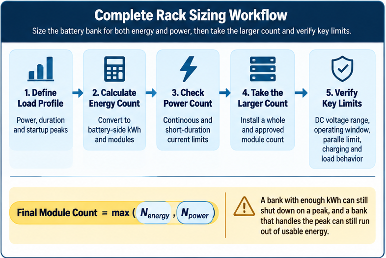
Use the largest whole-number lower bound from usable energy, continuous current and matched-duration peak current, then check whether that many modules can be connected within the approved system limits. A larger count that exceeds a permitted parallel quantity, bus rating or inverter input condition is not an implementable answer.
The table separates constraints that are often compressed into one capacity figure. Supply each row with values from the same load profile and a supported module configuration; its formulas are decision aids, not product-specific claims.
| Constraint | Required input and units | Calculation or pass criterion | Effect on module count |
|---|---|---|---|
| Usable energy | Battery-side kWh over the required interval; usable kWh per module | Round up required kWh divided by usable kWh per module | Sets the runtime lower bound |
| Continuous current | Required A at the lowest relevant DC voltage; allowed continuous A per module | Round up required A divided by allowable A per module, then check sharing | Sets the sustained-power lower bound |
| Timed peak | Peak A and duration; module and inverter ratings at matching duration | The proposed bank and upstream path must both carry that event | May increase count or require a different load/system design |
| Parallel and upstream limits | Approved module count, bus/feed ratings and inverter DC limits | Proposed count and resulting currents must stay within every applicable limit | Can invalidate an otherwise sufficient count |
| Recharge window | Energy removed, available charging power and time before the next event | Replacement energy must be available within the permitted charge conditions | May change the operating plan or require more bank capability |
Consider a hypothetical calculation yielding two modules for energy, three for continuous current and two for the timed peak. The preliminary answer is three modules, not an average of the three results. If the proposed wiring or equipment supports only two in that configuration, declaring a three-module bank would not resolve the design. The load peak, bank architecture or approved equipment would have to change. Parallel module energy may add while bank nominal voltage stays at the system's voltage, but upstream parts still have their own ratings, as the battery-bank wiring explanation makes clear.
The result is the smallest approved whole count that passes all constraints, or a finding that the proposed architecture cannot pass.
Recharge time matters when the bank must be ready for another event before all removed energy can be restored. In that case, a count that survives one discharge may fail the operating schedule; available charge power, module charge limits and the gap between events become additional constraints.
For a first approximation, divide the energy that must be returned by the charging power actually available to the battery. If 6 kWh must be replaced and only a hypothetical 1.5 kW reaches the bank, the energy-only lower estimate is four hours. Real recovery may take longer because charging power can be limited by the charger, BMS, temperature, state of charge or a later taper. This simple quotient is useful to expose an impossible schedule; it is not a complete charge curve or a promised completion time.
Ask what the load will do during recovery. If the bank must support the load while recharging, the charger first has to cover that simultaneous demand before it replenishes the deficit. If only part of the bank's operating window was used, the next event may require restoration to a defined readiness level rather than to an arbitrary full indication. If the required recovery interval is shorter than the allowable charging path can provide, adding modules might increase permissible aggregate charge acceptance in an approved parallel system, but it does not create charger power. The remedy could instead be a larger approved charger, longer recovery interval, reduced event demand or changed operating schedule.
For a single-event duty cycle, state that the count covers the first discharge only; a repeated cycle needs the recovery check above.
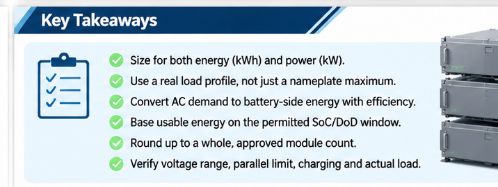
Run a controlled representative load from a recorded starting state of charge and observe the bank voltage, actual duration, module or branch currents and alarms. Compare those observations with the energy and current assumptions; revise the count or system design according to whichever limit appears first. A paper calculation becomes useful only when its boundary conditions can be recognized in the installed system.
Use a load profile that includes the sustained state and any relevant peak, rather than testing only a comfortable steady load. Record the start and end of the required interval at the load boundary used in the calculation. If the inverter stops before the target duration while branch current remains comfortably within its limits, inspect the usable-energy or cutoff assumptions. If a peak produces a BMS or inverter current alarm despite adequate remaining state of charge, inspect peak-duration ratings, the low-voltage current estimate and whether one branch carries more than its expected share. If the first event passes but readiness is not restored before the next, the recharge window is the limiting condition.
Voltage and current readings need context. A low bank voltage under heavy load can reflect state of charge and wiring drop together; measure at appropriate points and interpret the difference before attributing the entire effect to battery capacity. Unequal branch currents may indicate path differences or module state and should be evaluated under the same load. Do not increase the proposed parallel count merely to mask an incorrect connection or an unapproved configuration. The validation result should identify which of energy, continuous current, peak current or recharge is actually binding. That turns the next design revision into a reasoned change rather than a bigger battery guess.
If you are comparing a particular rack module against this method, use its published specifications and the intended load profile as the starting pair. Share only the required runtime, sustained and peak load, operating voltage range and proposed configuration for a focused product discussion; the calculated answer should remain visible here rather than being replaced by a request for a quote.
Related News

Nov. 07, 2026
Can a Home Battery Start and Run High-Surge Household Loads?
Learn why battery kWh alone cannot prove motor-start backup. Compare inverter surge duration, running demand, simultaneous loads and a supervised backup test.
Nov. 07, 2026
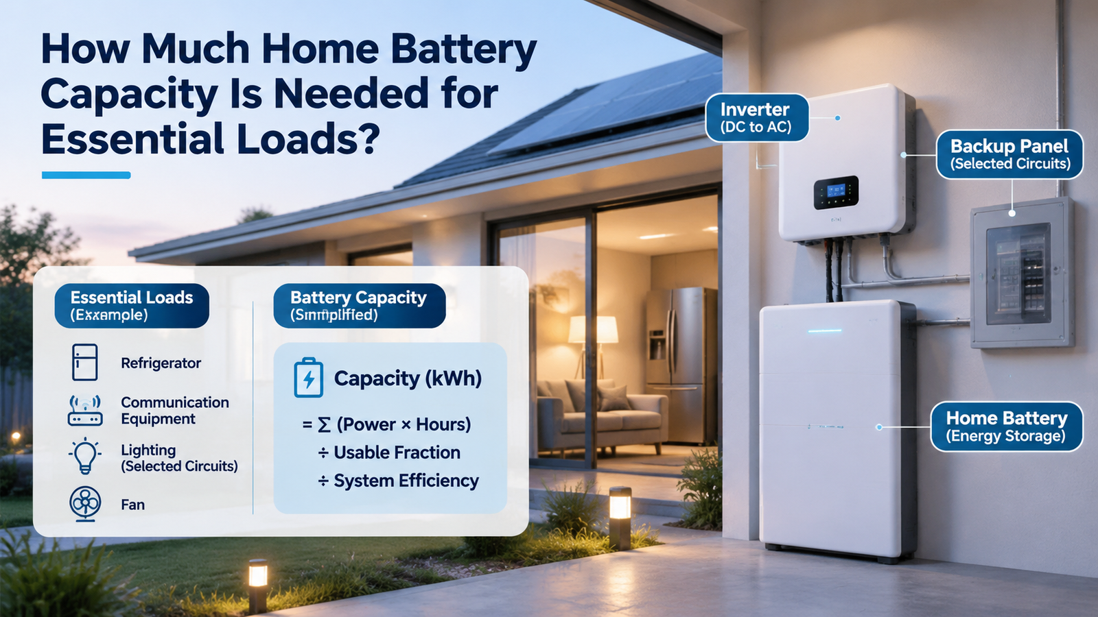
How Much Home Battery Capacity Is Needed for Essential Loads?
Calculate home battery capacity from essential-load power, duty cycle and outage hours. See a transparent kWh example and avoid double-counting losses.

Nov. 07, 2026
How Should a Home Battery Specification Sheet Be Read for Backup and Daily Use?
Compare home battery capacity, usable energy, continuous and peak output, charging limits and rating conditions before judging daily use or backup claims.

Nov. 06, 2026
Whole-Home Battery Backup or Critical-Load Backup: Which Scope Fits the Home?
Compare whole-home and critical-load battery backup by protected circuits, peak power, outage duration and load control to choose a realistic home backup scope.
Nov. 06, 2026
Can a Home Battery Provide Backup Power Without Solar Panels?
A home battery can provide backup without solar if grid charging, outage isolation and backup circuits are configured. Learn what limits runtime and recharge.
Nov. 06, 2026
How Does a Home Battery Storage System Work for a Household?
Follow the energy path through a home battery, inverter and controls. Learn how charging, daily discharge and outage backup differ before comparing systems.

Nov. 06, 2026
How Can A Weak Battery Be Distinguished From A Weak Golf Cart Battery Bank?
Compare like-conditioned unit and bank readings to separate one weak battery from broad bank loss, charging shortfall or connection trouble.
Nov. 06, 2026
How Should A Replacement Golf Cart Battery Bank Be Planned?
Decide whether one unit or the bank needs replacement, then specify voltage, fit, connections and first-charge checks before ordering.

Nov. 06, 2026
What Changes When A Golf Cart Battery Bank Is Converted To Lithium?
Map the battery bank, tray, charger, controller, gauge and accessory interfaces that change when converting a lead-acid golf cart to lithium.

Nov. 06, 2026
When Does Lithium Make Sense Instead Of Lead Acid For A Golf Cart?
Compare lithium and lead acid for the same golf-cart duty, charging routine, maintenance capacity and ownership horizon before deciding whether a switch is worthwhile.

Nov. 06, 2026
How Can Peak Current Demand Be Matched To A Golf Cart Battery?
Compare a golf cart’s acceleration and hill-load current by duration with battery continuous, pulse and protection ratings under matching conditions.