

Nov. 06, 2026
A rack battery and inverter communicate successfully only when the complete data chain works: the correct battery interface is wired to a supported inverter or gateway, both devices interpret the same messages, and the inverter responds to the battery's operating limits. A DC connection can deliver power while this control chain is absent. For an integrator, the useful test is therefore neither matching plugs nor a lit communication icon. It is whether battery state and limits reach the control device, whether charge or discharge behavior follows those limits, and whether a documented loss-of-communication response occurs. The details depend on the selected battery, gateway, inverter and firmware combination; the physical and functional distinctions below provide a way to evaluate that combination without treating any one manufacturer's wiring as universal.
The battery's positive and negative conductors carry DC energy; a separate BMS interface carries information that can describe the battery and, in a supported closed-loop system, constrain what the inverter or charger does. These paths meet in the overall system but do different jobs. A voltmeter can show battery voltage at the inverter DC input even when the communications cable is disconnected, miswired, or speaking an unsupported protocol.
A rack module contains cells, monitoring electronics, DC terminals and a communication interface. In a bank, the DC terminals connect through an approved protected path to a bus and then to the inverter. The BMS monitors electrical and thermal conditions within the battery, while an upstream controller may receive selected data through CAN, RS485 or a gateway. The EG4 connection guide depicts separate power and communication connections for its rack modules. That physical separation is the first clue when a system powers up but offers no usable battery data.
Voltage, current, temperature, state of charge and alarms describe conditions; permitted charge or discharge current and voltage limits can influence equipment behavior when the selected protocol and controller support them. The exact field set is a property of a particular integration, not of the words CAN or RS485. A state-of-charge value tells an operator how full the bank is estimated to be, but it does not by itself tell a charger to reduce current. A charging limit is an instruction or constraint that the controller must receive, understand and apply. The Victron–Discover integration guidance shows this distinction by describing battery data and charge-control requests in a supported arrangement. In a drawing, label the battery-to-controller signal as data or a limit request; do not draw it as if current were flowing through the communications cable.
CAN or RS485 ports form a usable chain only when the endpoints agree on wiring, link configuration, message meanings, device settings and supported software versions. The interface name identifies an electrical communication family, not an interchangeable battery language. An inverter can detect activity at a port yet fail to recognize the battery or act on its limits.
Start at the actual endpoints. The battery, nominated master module or gateway must connect to the inverter's intended battery-data port, not merely to any socket with the same shape. The cable must use the pin assignment specified for that pairing; termination and communication settings must fit the selected bus arrangement. A link error at this layer often appears as no recognized battery or no updating values. Changing a DC bus cable cannot repair that fault because it does not change the data path. At the next layer, the receiver must decode the message set and identify the battery profile. A display that reports electrical link activity without meaningful voltage, state of charge or limits has not passed that test.
The Victron compatibility instructions for Discover specify a particular battery, interface and configuration. They illustrate why support must be judged as an exact pairing: the controller expects a defined source of battery information and has a defined response. Another rack battery's CAN connector cannot be substituted solely because the connector fits. Even a firmware change can alter the supported profile or setup procedure, so the integration's version scope matters when interpreting a successful bench test.
| Layer | Endpoints and required relationship | Meaningful observation | If it fails |
|---|---|---|---|
| DC power | Protected battery terminals to inverter DC input; correct polarity and design voltage | Voltage is present at the intended DC input | Correct isolation, protection or the DC connection; this says nothing about BMS data |
| Data connection | Battery master or gateway to the intended inverter or control port; pinout and link settings agree | Battery identity and values appear and update | Repair the cable, port assignment or link configuration |
| Message profile | The specific device and software combination uses the same battery messages | State and operating limits have plausible, changing values | Select a supported profile or resolve the device/version pairing |
| Control response | The controller receives and uses the limits in the selected mode | Charger behavior follows a permitted limit during a controlled test | Examine control mode and the controller's use of received data |
| Lost link | Response follows the documented pairing, rather than an assumed universal fallback | A controlled interruption produces the documented response | Stop acceptance and resolve the pairing or configuration |
The table separates physical connection, decoded data and acted-on limits; a pass at one layer cannot substitute for the next.
A live port can carry electrical traffic that the inverter cannot translate into an accepted battery limit. Incorrect battery profile selection, mismatched message definitions, unsupported firmware or a controller operating in a manual mode can all leave charging under its preset rules despite apparent traffic. The practical distinction is between “the receiver hears something,” “the receiver displays a valid battery state,” and “the receiver changes its action when a valid limit changes.” These are separate observations, not synonyms. If state appears but control does not follow it, focus on the message-to-control part of the chain instead of replacing a cable that already carries data. If no state updates at all, move back toward port selection, wiring and link settings.
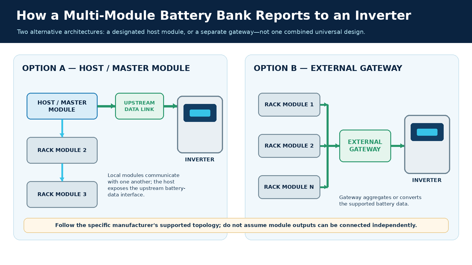
A multi-module bank usually needs one defined upstream representation: the modules exchange information locally, and a nominated master or a gateway presents bank-level data to the inverter. Which device takes that role depends on the supported battery architecture. Connecting every module's communication output independently to an inverter port is not a safe default.
In one architecture, a chain of rack modules communicates internally and a designated host module exposes the upstream interface. The EG4 connection guide describes its own host and parallel communications arrangement. In another, a battery network feeds a separate interface device; the Discover–Victron guidance uses a LYNK II interface with the control system. These examples describe alternative roles, not components that can be mixed into one universal schematic. Their addressing and wiring details remain specific to their respective devices.
Aggregation matters because the inverter acts on a bank, not on an isolated module's report. A missing module in the local network can make the reported state or available current differ from the physical collection of installed modules. A duplicate address or wrong communications route can similarly prevent the upstream controller from seeing the intended group. The exact consequence is product-specific, but the integration question is common: which device reports the bank, how does it know which modules belong to the bank, and what observable indication shows that all intended modules are represented? This data coordination is distinct from whether the parallel DC paths share current correctly; the latter requires its own electrical design.
A useful commissioning comparison is the count and identity of installed modules versus what the battery network reports. Then look at the upstream inverter view. If the local network sees the modules but the inverter does not, the failure is likely on the upstream gateway, profile or port side rather than the internal module chain. If the bank representation itself is incomplete, investigate that local chain before interpreting an apparently normal inverter screen. This reasoning avoids assuming that a single displayed state-of-charge value proves the whole rack is online.
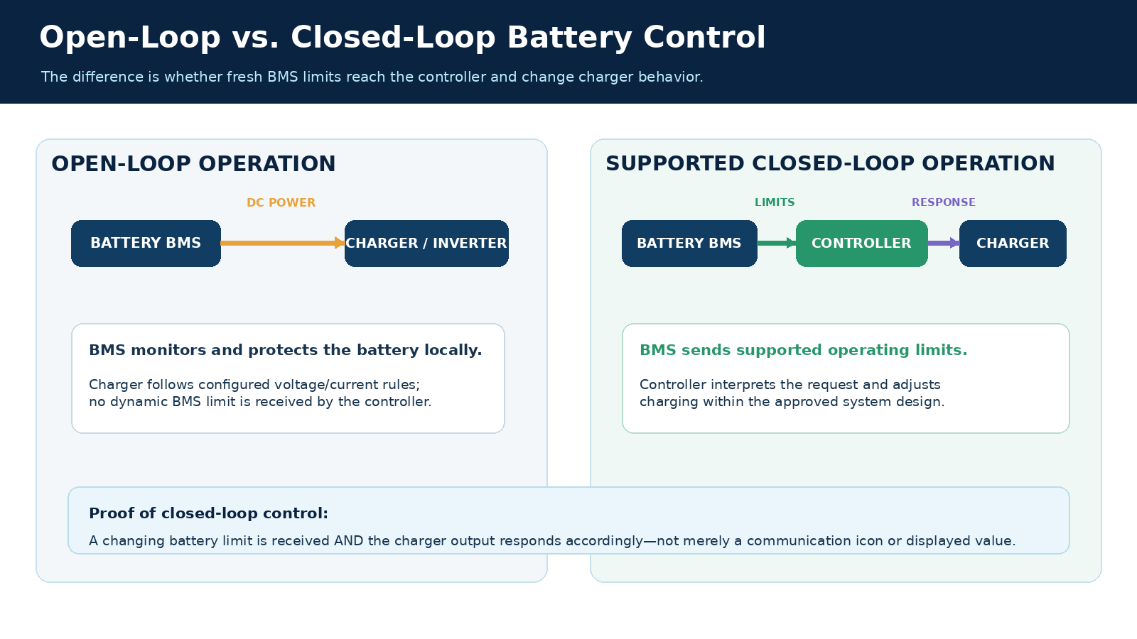
In open-loop operation, the charger follows configured voltage and current rules while the battery retains its own protective functions; in a supported closed-loop arrangement, battery data can dynamically constrain the charger or inverter through the control system. The operational difference is whether fresh BMS limits can change upstream behavior, not whether the battery has a BMS at all.
Consider a charging interval. The BMS observes the cells and derives an allowed operating envelope. In a compatible closed-loop arrangement it sends the relevant limit to the upstream controller, which must translate that request into a charge-current or voltage response. If the permitted current falls as the battery approaches a boundary, the controller should reduce charging according to the supported design. A screen showing the new value is only partial proof; the measured or reported charger output must also respond. The Discover integration guidance describes this interaction for its Victron pairing. It does not establish the same behavior for every inverter that carries a CAN port.
In open loop, installers enter settings appropriate to the chosen battery and equipment. The BMS still monitors and protects the battery, but the charger does not acquire dynamic battery instructions merely because its DC terminals are connected. A local BMS protection event is not an alternative control strategy to rely on for routine charging: it is a protective boundary. The selection of actual charging values is a separate battery and charger configuration task. Here the point is the causal link: a changing battery condition can either be communicated and acted upon by the controller, or remain outside its direct control loop.
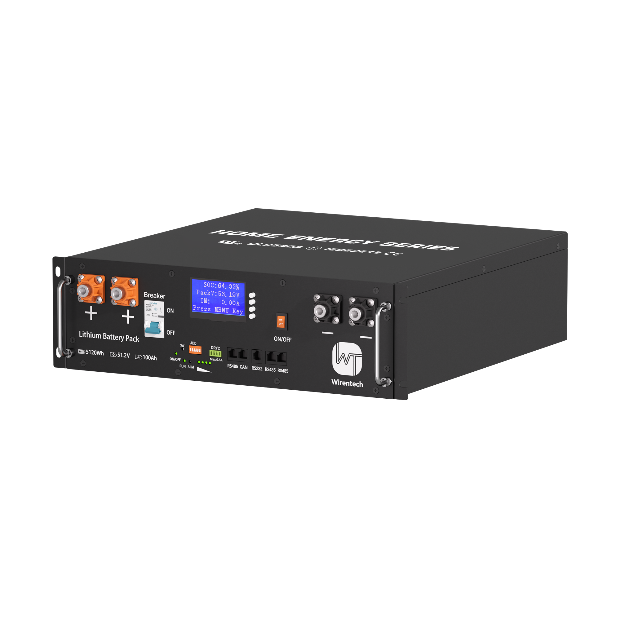
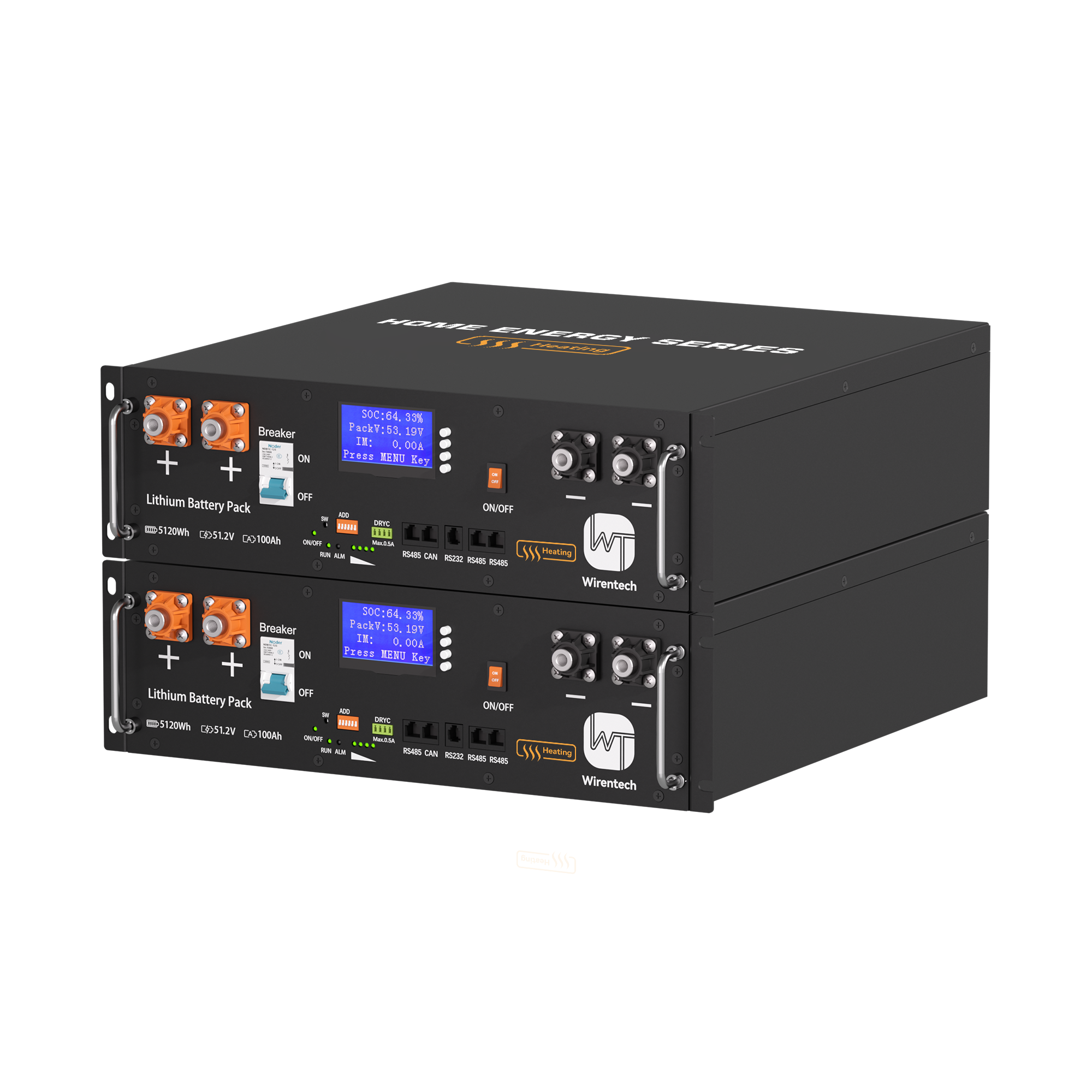
The published WT5100 rack battery interface details list CAN and RS485 and a protocol description for that model. They provide a starting point for inspecting its stated interface, not evidence that a particular inverter, firmware version or installation will operate closed loop. That conclusion requires the exact pairing and a behavioral test.
The lost-link response must follow the documented behavior of the exact integration. In the published Discover AES, LYNK II and Victron closed-loop arrangement, charging stops if communications are lost. That is a specific protective response, not a promise that all batteries or inverters stop, continue, or switch automatically to preset values. A controller may expose an alarm, a stale value, a fallback mode or a stop state according to its design. The acceptance question is whether the observed transition matches the selected equipment's stated behavior and whether recovery restores valid data before normal control resumes. Test interruption only through the approved procedure for the equipment; an unscripted live cable pull can create a separate electrical or operational risk. A mismatch between expected and observed response is a failed integration test even if charging appeared normal before the interruption.
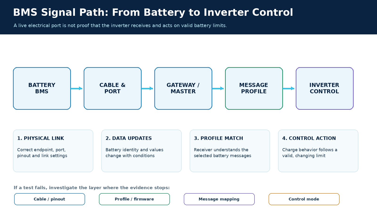
Verify the link by moving from recognized battery data to observable control behavior, then to the documented fault and recovery behavior. A link light, static state-of-charge number or one successful charging interval proves only part of the chain. The test should use the selected equipment's permitted procedure and a condition in which a change in battery request can be observed without exceeding its approved operating range.
First establish a baseline with the approved DC and data connections in place. Identify the battery or gateway as the control system sees it and compare that identity with the installed bank. Check that voltage, current, state of charge and any available alarms update as conditions change, rather than remaining frozen at plausible-looking values. A stale field can be more misleading than a blank one because it may appear valid while the controller has stopped receiving fresh messages. For a multi-module rack, compare the reported module population with the physical bank before using an aggregate limit as an acceptance result.
Next identify which values represent requests or limits. The Victron–Discover configuration provides an example of a controller that receives charge constraints from the battery side. In a controlled test, observe both the reported request and the corresponding charger behavior. If the request tightens while charger output remains governed only by an old manual setting, the data path may work but the control mode or mapping does not. If the charger changes for an unrelated reason, such as its own voltage ceiling, that observation alone does not prove it followed the BMS. The decisive test relates the battery's indicated limit to a compatible control response under a condition where the limit can matter.
Look at alarms with the same discipline. A displayed warning must have a clear source and timestamp or fresh-state indication; otherwise it can represent an old event or a local inverter alarm unrelated to the battery. Where the supported integration exposes battery alarms, check that they propagate to the intended supervisory device. A battery's local protection should not be treated as proof of upstream coordination. The system may protect itself yet still lack the planned closed-loop response.
Test loss and restoration according to the selected manuals and the site's safe procedure. For the specific Discover–Victron pairing above, the expected charging stop is a concrete acceptance observation. A different pairing needs its own documented expectation; copying that result into an unrelated system would be an unsupported safety claim. On restoration, look for renewed, changing battery values and the proper return of charger control. An icon that simply reappears does not establish that limits are current or acted upon. Record the initial state, the induced event, the control response and the recovery state so another engineer can distinguish a genuinely accepted link from an incidental display change.
If a test fails, use the point of failure to choose the next check. No recognized battery or updating data suggests the data endpoint, cable, link settings or module-network representation. Data without usable limits suggests a protocol or profile mismatch. Valid limits without a charger response suggests the receiving control mode or its connection to the charger. Unexpected behavior after link loss suggests the documented fault configuration or the tested pairing is wrong. These branches make the immediate integration decision actionable; they do not replace a full service investigation into a deployed system.
The usable outcome is a demonstrated chain from battery state to controller action, with an observed behavior at interruption and restoration. When a specific inverter pairing cannot pass that sequence, treat it as unaccepted closed-loop integration even if DC power flows. The battery might still be usable in an explicitly designed open-loop arrangement, but that is a different approved configuration with its own charging settings and acceptance criteria. The distinction prevents a superficial “connected” result from being mistaken for functioning BMS control.
Related News
Nov. 07, 2026
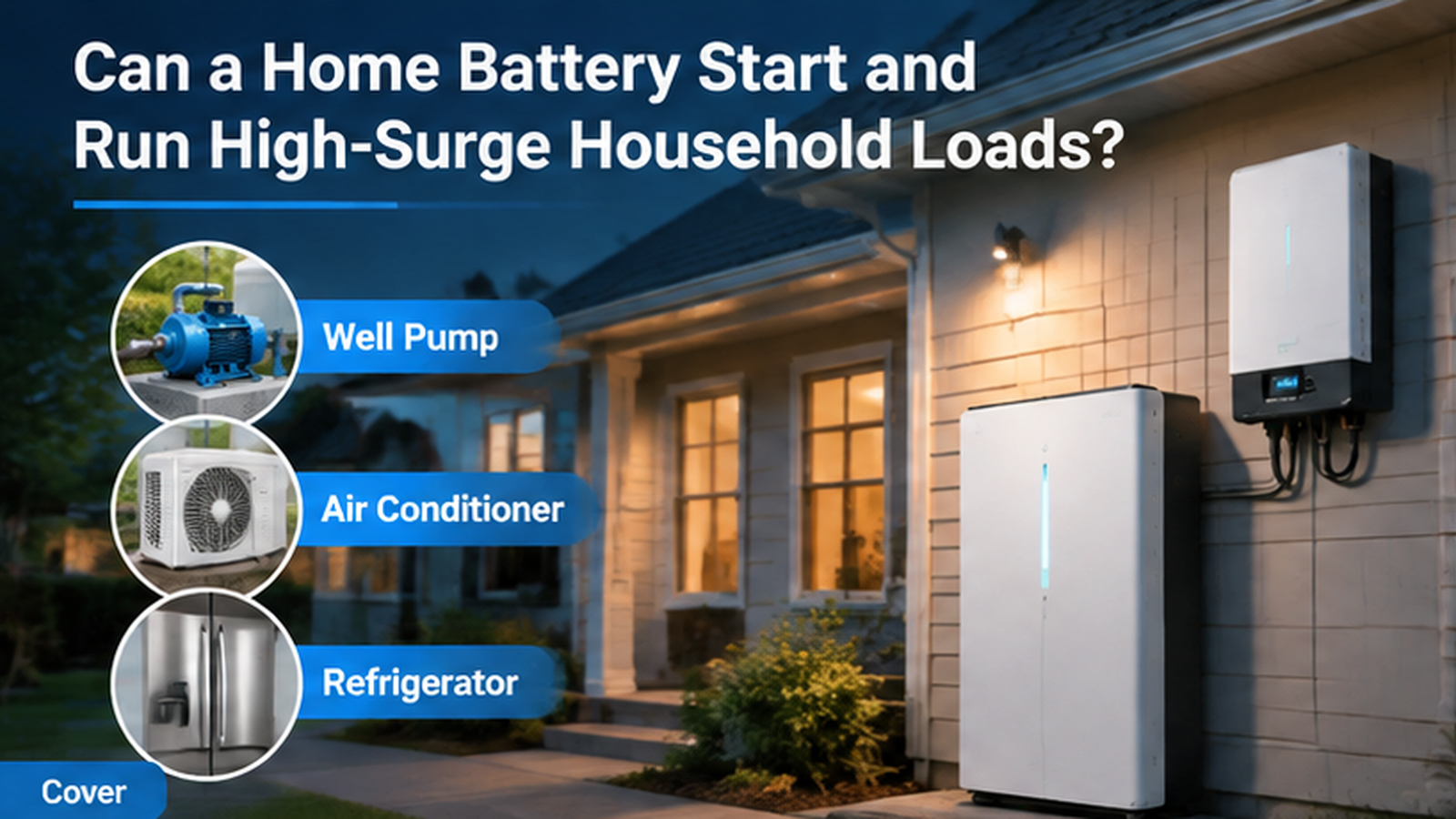
Can a Home Battery Start and Run High-Surge Household Loads?
Learn why battery kWh alone cannot prove motor-start backup. Compare inverter surge duration, running demand, simultaneous loads and a supervised backup test.
Nov. 07, 2026
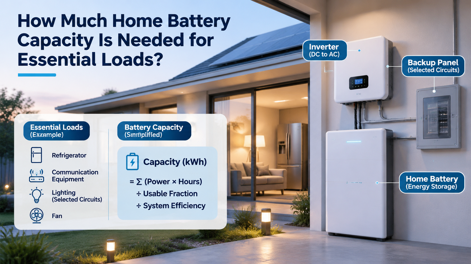
How Much Home Battery Capacity Is Needed for Essential Loads?
Calculate home battery capacity from essential-load power, duty cycle and outage hours. See a transparent kWh example and avoid double-counting losses.

Nov. 07, 2026
How Should a Home Battery Specification Sheet Be Read for Backup and Daily Use?
Compare home battery capacity, usable energy, continuous and peak output, charging limits and rating conditions before judging daily use or backup claims.
Nov. 06, 2026
Whole-Home Battery Backup or Critical-Load Backup: Which Scope Fits the Home?
Compare whole-home and critical-load battery backup by protected circuits, peak power, outage duration and load control to choose a realistic home backup scope.
Nov. 06, 2026
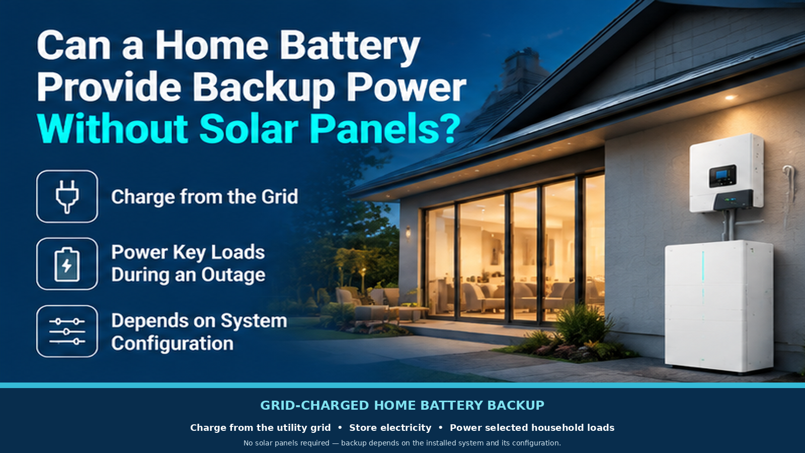
Can a Home Battery Provide Backup Power Without Solar Panels?
A home battery can provide backup without solar if grid charging, outage isolation and backup circuits are configured. Learn what limits runtime and recharge.
Nov. 06, 2026
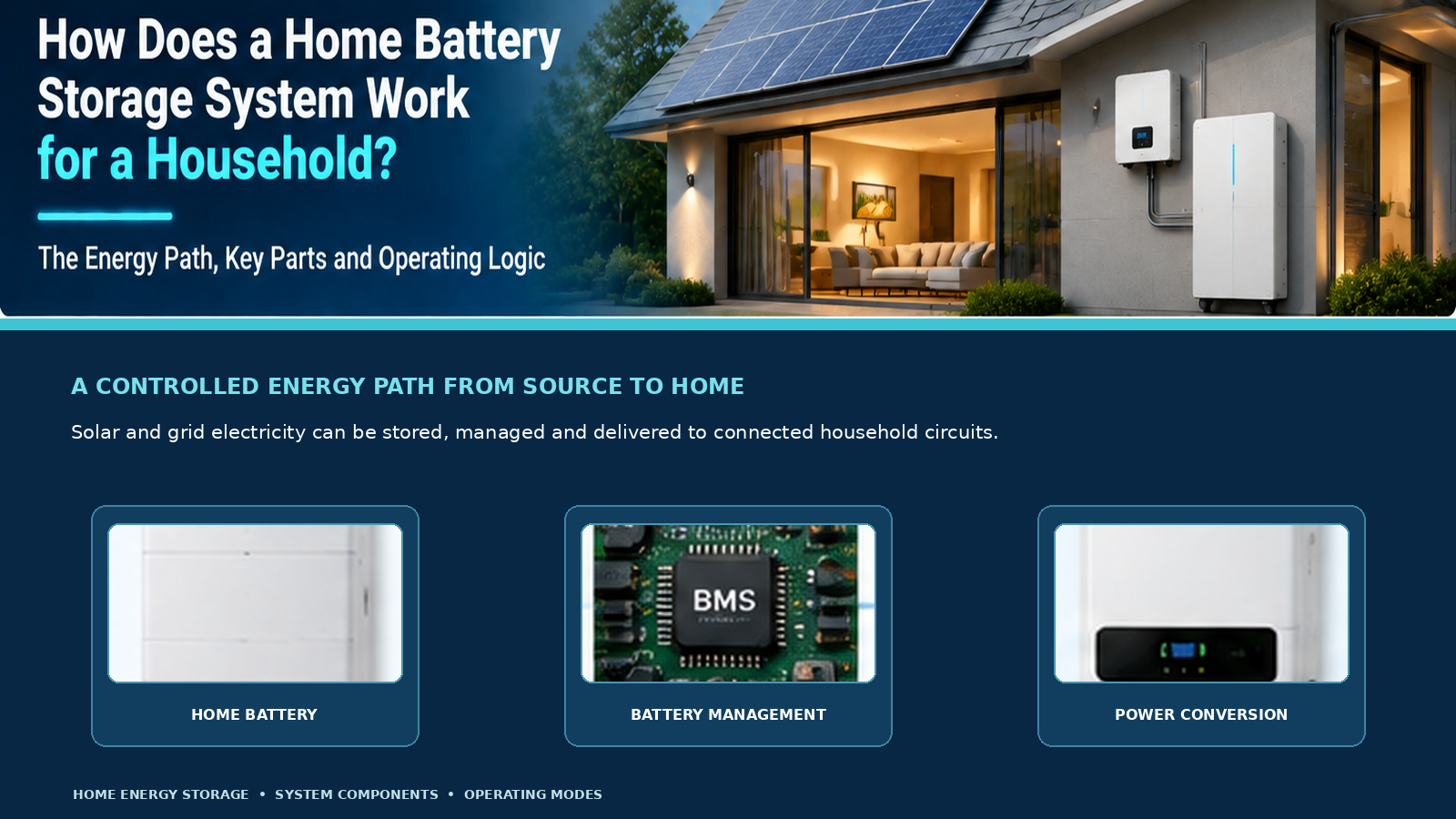
How Does a Home Battery Storage System Work for a Household?
Follow the energy path through a home battery, inverter and controls. Learn how charging, daily discharge and outage backup differ before comparing systems.

Nov. 06, 2026
How Can A Weak Battery Be Distinguished From A Weak Golf Cart Battery Bank?
Compare like-conditioned unit and bank readings to separate one weak battery from broad bank loss, charging shortfall or connection trouble.
Nov. 06, 2026
How Should A Replacement Golf Cart Battery Bank Be Planned?
Decide whether one unit or the bank needs replacement, then specify voltage, fit, connections and first-charge checks before ordering.

Nov. 06, 2026
What Changes When A Golf Cart Battery Bank Is Converted To Lithium?
Map the battery bank, tray, charger, controller, gauge and accessory interfaces that change when converting a lead-acid golf cart to lithium.
Nov. 06, 2026
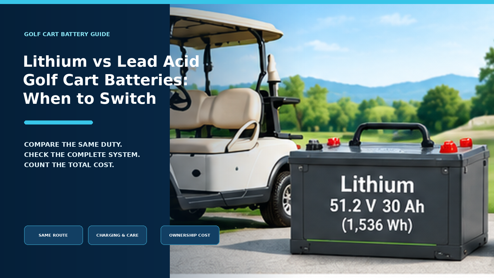
When Does Lithium Make Sense Instead Of Lead Acid For A Golf Cart?
Compare lithium and lead acid for the same golf-cart duty, charging routine, maintenance capacity and ownership horizon before deciding whether a switch is worthwhile.

Nov. 06, 2026
How Can Peak Current Demand Be Matched To A Golf Cart Battery?
Compare a golf cart’s acceleration and hill-load current by duration with battery continuous, pulse and protection ratings under matching conditions.