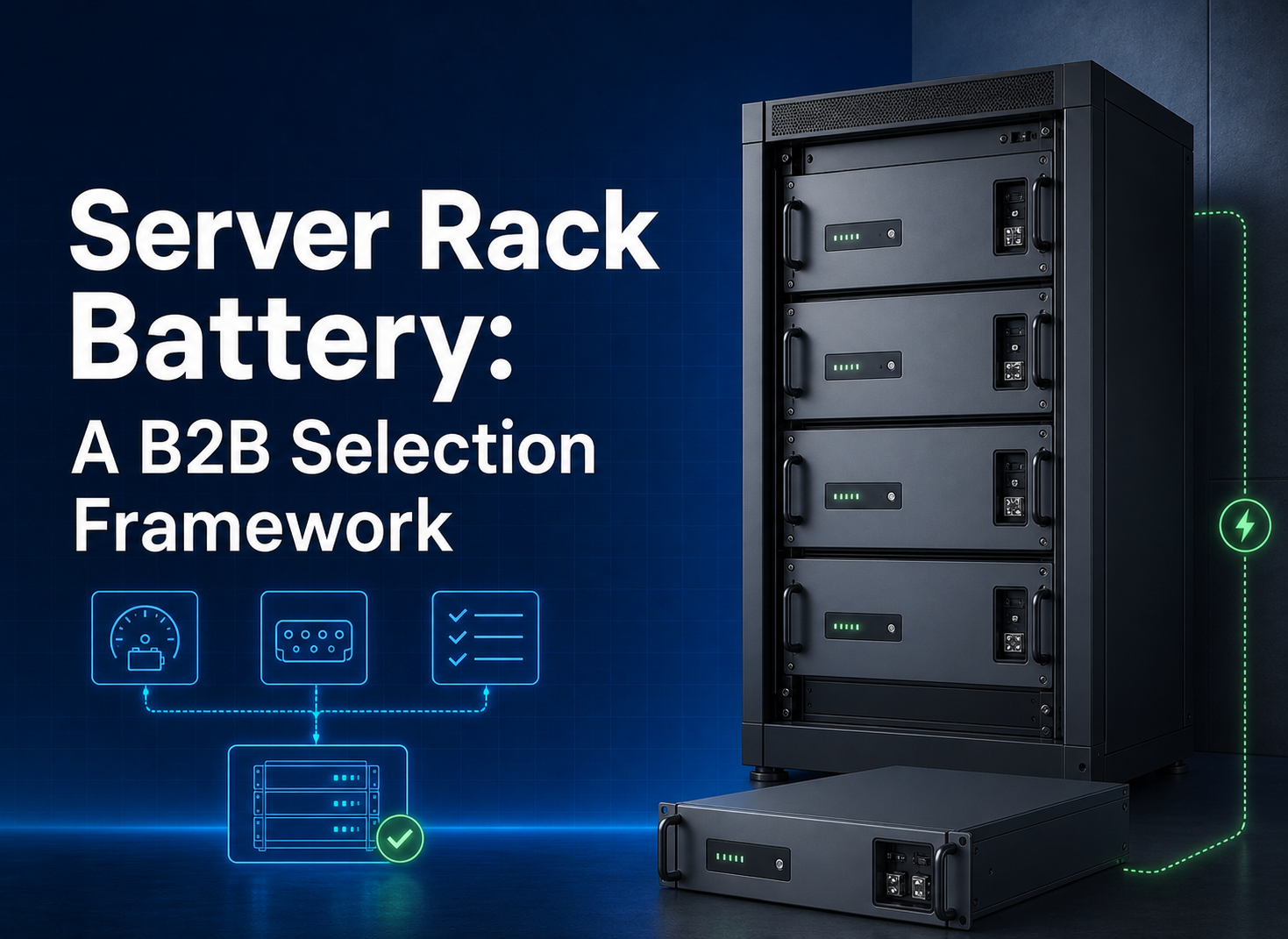
A 48v server rack battery should be approved as part of a defined DC platform, not as an interchangeable “48 V box.” For a safe, scalable installation, verify the inverter’s full battery-voltage window, continuous and transient DC current, required usable energy, rack envelope, protection scheme, communication protocol, environmental limits, and model-specific evidence. The procurement judgment is simple: choose the configuration whose interfaces can be tested and repeated, even if another quotation looks easier to compare from its headline Ah value.
The market phrase “48 V” often groups equipment with different nominal voltages and charge limits. That is useful for discovery but incomplete for engineering. A solar installer, UPS integrator, or server-room designer must convert the phrase into controlled values before asking a supplier to size modules, cables, busbars, or protection.
Define the 48 V platform before selecting modules
Start with the inverter or DC load, because it sets the permitted operating window. Record minimum start voltage, normal operating range, charging ceiling, low-voltage shutdown behavior, pre-charge requirements, and the current limits expected during charge and discharge. Do the same for any DC/DC converter, UPS, or rectifier connected to the bus. A nominal label cannot show whether those windows overlap across temperature, state of charge, and fault conditions.
The requirement sheet should distinguish nominal voltage from maximum charge voltage and minimum permitted operating voltage. It should also state who owns the final settings: battery supplier, inverter supplier, EPC, or commissioning contractor. If no party owns the interface, the project can arrive on site with individually plausible components that cannot be commissioned together.
|
Platform input
|
Why it changes the decision
|
Evidence to request
|
|
Inverter battery window
|
Determines whether the battery can charge, discharge, and recover correctly
|
Model and firmware-specific configuration record
|
|
Continuous and transient load
|
Sets current, conductor, protection, and thermal requirements
|
Time-current duty profile with test conditions
|
|
Autonomy target
|
Converts the load into a usable-energy requirement
|
Load schedule, losses, reserve, and ageing assumptions
|
|
Rack and room constraints
|
Controls module count, service access, cooling, and cable routing
|
Dimensioned layout and installation review
|
Separate energy sizing from DC current sizing
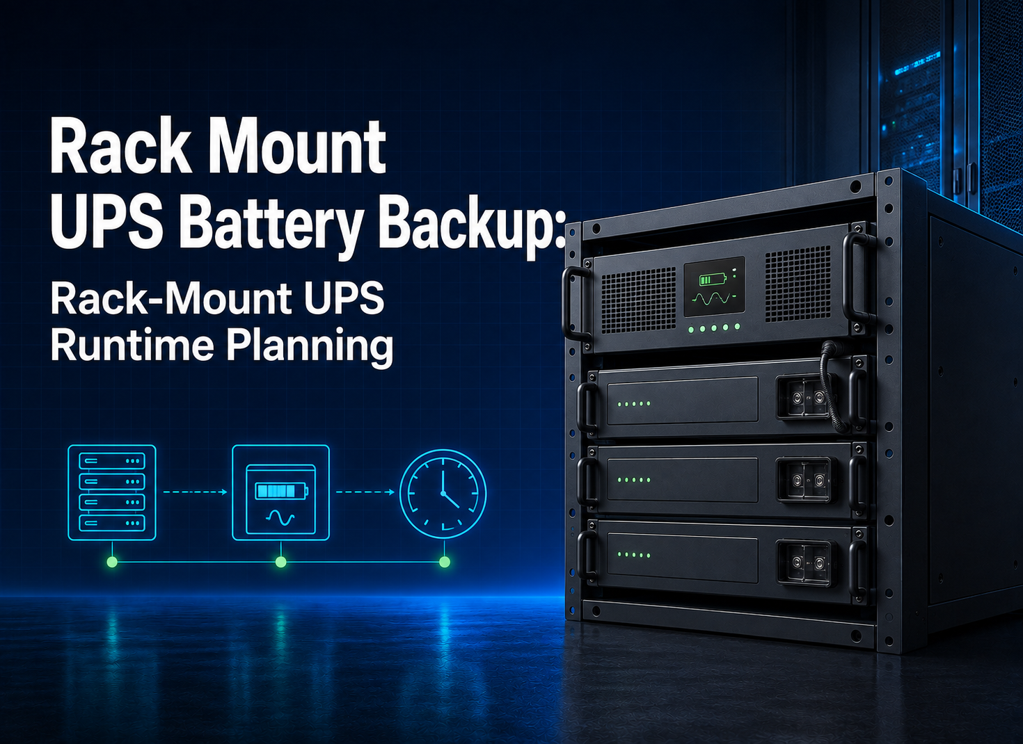
Energy answers “for how long”; power and current answer “how hard.” Calculate the AC energy needed by the protected loads, allow for conversion losses and an agreed reserve, then translate the result into required usable DC energy. Do not treat nominal kWh as usable kWh unless the applicable documentation defines the operating window and assumptions.
Current is the cross-check that buyers often miss. The simple relationship is current equals power divided by voltage, but the design current must also consider conversion efficiency, low-voltage operation, simultaneous loads, motor or compressor starts, and any time-limited overload. As voltage falls, current for the same power rises. The BMS limit, module connectors, busbars, cables, fuses or breakers, isolation devices, and inverter terminals must all be evaluated against the same duty profile.
- List each protected load, its running power, start behavior, and expected duration.
- Define the required reserve rather than assuming all nominal energy is available.
- State continuous and time-limited current separately, with duration and conditions.
- Model cable voltage drop at the longest route and lowest design voltage.
- Preserve the calculation as part of the commissioning baseline.
Treat rack fit as an interface, not a product label
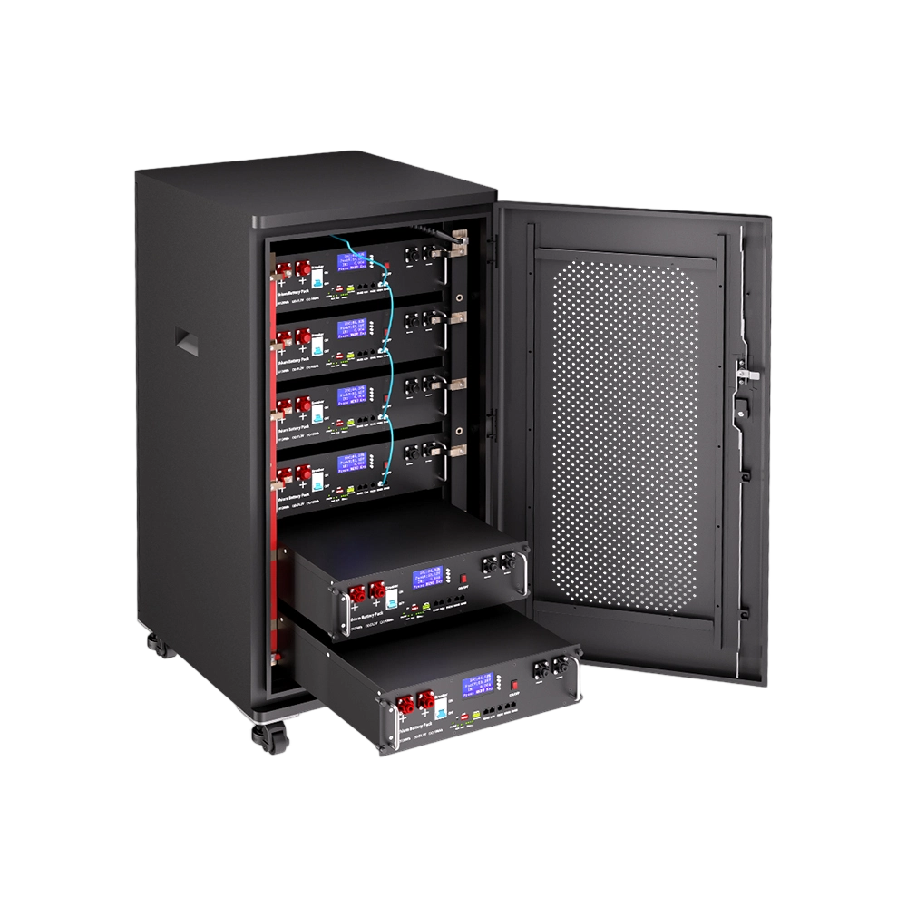
A “19-inch rack” description does not settle module depth, U-height, rail type, mounting-hole pattern, loaded mass, front and rear clearance, cable bend radius, or service method. Obtain a controlled mechanical drawing and compare it with the actual cabinet. Include the space taken by busbars, breakers, communications, ventilation paths, lifting aids, and isolation access.
The layout should let technicians remove one module without disturbing energized conductors or unrelated units. Heavy modules may require a shelf, slide, lifting process, or two-person handling rule. Confirm floor loading, rack anchorage, stability, and local seismic requirements with the responsible structural professional. Product literature is not a structural approval for a specific room.
Thermal management also belongs in the interface review. Record inlet conditions, expected losses, module spacing, airflow direction, room cooling, derating rules, and alarm actions. Avoid promising that a chemistry label makes ventilation or fire planning unnecessary; the site design and applicable rules govern those decisions.
Engineer the parallel DC path before scaling capacity
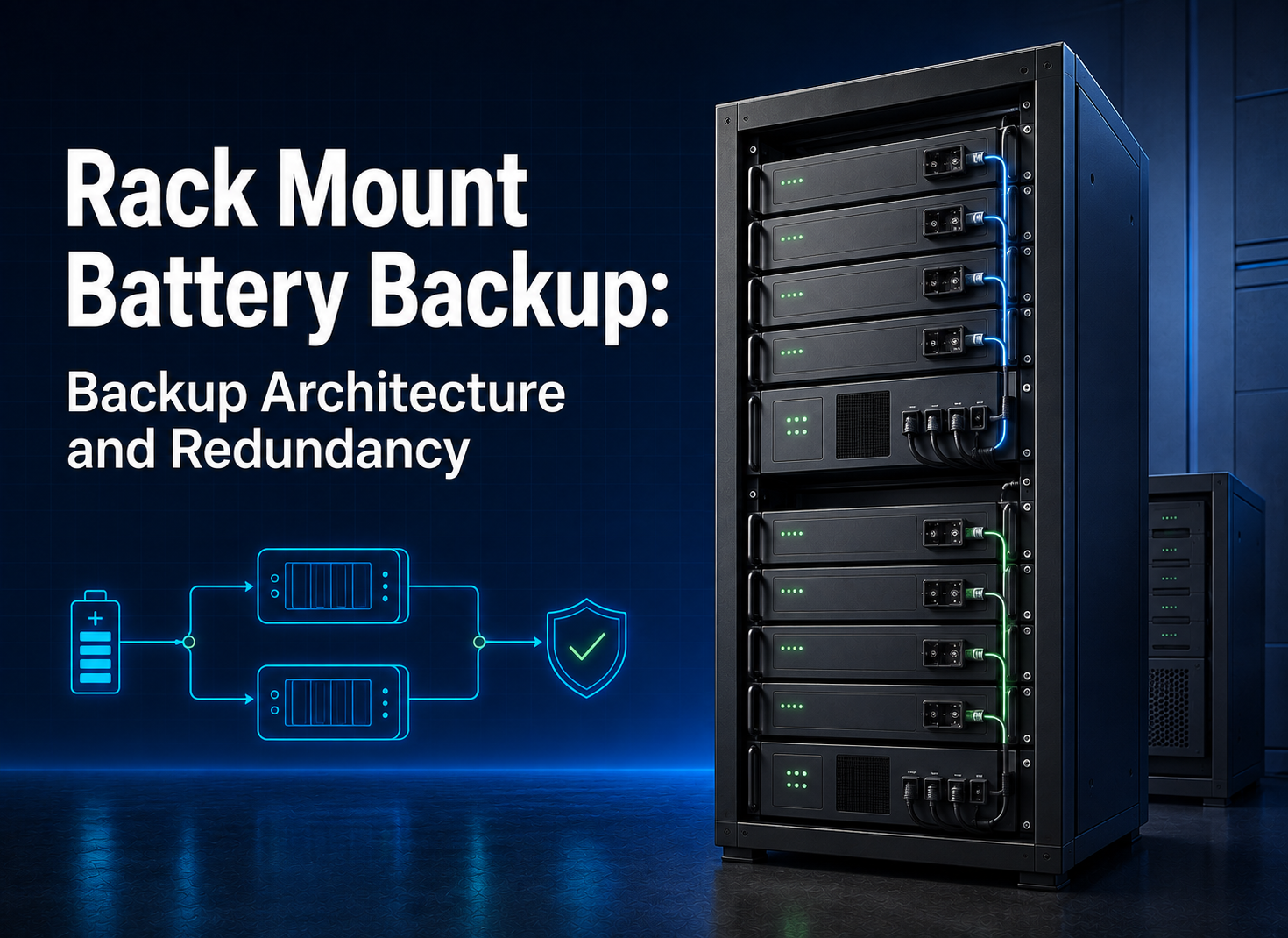
Parallel connection is a system topology, not merely a module feature. Unequal cable resistance, inconsistent state of charge, mixed firmware, different ageing histories, or asymmetric busbar placement can produce uneven current sharing. Specify equal-path or engineered busbar arrangements, branch protection, isolation, polarity controls, and a commissioning method that verifies sharing under representative load.

Do not assume a maximum parallel count from a generic brochure or a manual for another model. Request the validated limit for the exact battery model, BMS firmware, master/slave logic, communication topology, busbar design, and protection scheme. A system should be scaled only from model-specific documentation and a verified integration design.
|
Parallel-system question
|
Weak answer
|
Acceptable procurement evidence
|
|
How many modules?
|
“Up to many units”
|
Exact model, firmware, topology, validated count, and limitations
|
|
How is current shared?
|
“Common busbar”
|
Drawing, conductor schedule, branch protection, and load-test data
|
|
What happens after a fault?
|
“BMS protects it”
|
Isolation sequence, alarm behavior, recovery method, and acceptance test
|
|
Can old and new modules mix?
|
“Same voltage”
|
Written age-mixing policy and state-of-charge equalization procedure
|
Validate CAN or RS485 as a complete protocol chain
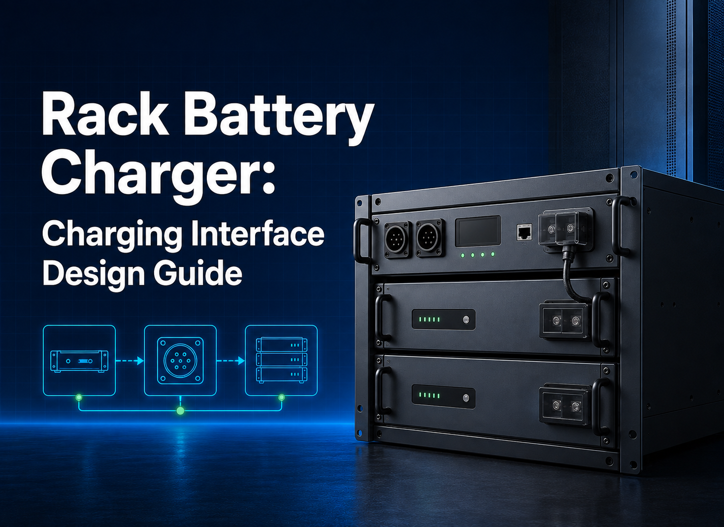
An interface name is not a compatibility result. Compatibility depends on protocol version, pinout, baud rate, termination, addressing, battery firmware, inverter firmware, operating mode, and tested behavior. Request a matrix for the exact equipment combination and date. If the supplier cannot provide one, plan a bench test before procurement release.
The test should observe charge and discharge limits, state-of-charge reporting, alarms, shutdown, restart, sleep and wake behavior, and communication-loss response. Record which device is the control authority and what happens if messages stop. Where closed-loop communication is not used, document the voltage-control strategy and the limitations accepted by the system designer.
Interface information is model-specific. A communications list in one battery manual must not be generalized to another rack product or interpreted as plug-and-play compatibility with a named inverter. Request the interface and protocol documentation for the exact model being ordered.
Build compliance and transport checks around the exact model
Certification language must follow document scope. A transport test summary does not approve a stationary installation, and a recognized component is not the same as a listed complete system. Ask for the file, report number, model, applicant or manufacturer role, issue date, revision, and any conditions tied to mark use. Compare those fields with the ordered model and nameplate.
For thermal-runaway evaluation, UL 9540A refers to a test method and report context, not a stand-alone product certification. Buyers should request the report applicable to the exact cell, module, unit, and installation configuration, including laboratory, date, and system boundary, rather than accepting a general “certified” statement or assuming that another product's report applies.
UN 38.3 documentation should also be model-specific and current for the shipping configuration. It supports transport review; it does not prove inverter compatibility, installed-system safety, cycle life, or warranty.

Use the product page as a technical handoff
For buyers whose duty profile aligns with a higher-capacity rack format, the 51.2V 200Ah 10kW LiFePO4 Rack Mounted Battery LFP Battery page can be used for initial product-family screening. That published name identifies the product; it does not by itself prove usable energy, continuous power, cycle life, parallel limit, compatibility, or project compliance.
The buyer should request the current datasheet, drawing, BMS information, protocol file, model-scoped transport and compliance documents, warranty terms, and change-control process. Keep any 100Ah requirement separate: the rack form and voltage family may be relevant, while capacity differs. Do not imply that the 200Ah product page is evidence for a 100Ah module.
Record the response in a one-page interface schedule. For each voltage, current, communication, mechanical, environmental, and evidence requirement, name the supplier document, revision, exception, responsible reviewer, and validation test. This compact schedule helps procurement distinguish a confirmed interface from a promising but unanswered feature and gives commissioning teams a traceable starting point.
Commission the platform against measurable acceptance criteria
Commissioning should be written before shipment. Begin with document and nameplate verification, insulation and polarity checks where applicable, torque records, protective-device settings, addressing, firmware versions, and state-of-charge alignment. Energize in a controlled sequence, then test charging, representative discharge, alarms, isolation, communication loss, emergency shutdown, and restart.
Measure current sharing across parallel branches and compare it with the agreed tolerance. Record bus voltage at the inverter and at the battery under load so cable drop is visible. Confirm that the inverter obeys the battery limits—or document the alternative control method. Save settings, logs, photographs, and sign-off in a commissioning pack linked to the serial numbers installed.
Acceptance should have a clear exception process. A temporary workaround is not a passed test. If firmware, cable layout, protection, or environmental conditions differ from the approved baseline, record the deviation, owner, risk decision, and retest requirement.
Release a sample as a controlled platform baseline
A sample order is valuable only when it answers the platform’s unresolved questions. Define the sample’s exact model, hardware revision, BMS firmware, communication protocol, settings, connectors, cable set, protective devices, rack position, and intended inverter combination. Mark which attributes are fixed for the pilot and which remain supplier-proposed. Without that configuration sheet, a successful test may be impossible to reproduce in a volume order.
The pilot plan should connect each risk to a test. A voltage-window concern needs charge, discharge, low-state-of-charge, and recovery observations. A current concern needs a documented load and duration. A communications concern needs normal and interrupted messaging. A rack concern needs fit, handling, cable access, and thermal review. A parallel concern needs current-sharing and fault-isolation criteria at the proposed scale—not a marketing maximum.
After testing, issue a baseline approval with open items clearly separated from passed items. Capture serial numbers, photographs, data logs, measurement equipment, ambient conditions, test personnel, and approvals. If the supplier proposes a different cell, BMS revision, firmware, connector, enclosure, or internal layout for production, require an impact statement and identify which tests must be repeated.
The production purchase specification should reference this baseline and require shipment-level evidence: configuration declaration, firmware and settings, traceable electrical results, labels, document revisions, packaging checks, and approved deviations. This turns “same model” into a verifiable release condition and reduces the chance that an apparently minor substitution changes inverter behavior or installation fit.
Before authorizing volume, repeat the most decision-critical test with the production-intent unit and normal project personnel. That final check exposes differences between an engineering demonstration and the workflow the installer, warehouse, and commissioning team can actually repeat.
Compare suppliers by repeatability, not factory slogans
A supplier comparison should reward controlled responses: model-specific documents, an interface owner, clear exceptions, revision control, traceable inspection records, and a workable change process. Do not infer factory ownership, production capacity, MOQ, sample time, lead time, or warranty from website language. Those items remain subject to current documentary and contractual confirmation.
Ask for the model-specific control plan, inspection records, calibration status, end-of-line test fields, nonconformance process, serial-number traceability, and release authority. A useful pilot order verifies that the proposed evidence can be produced consistently, not just that one sample powers on.
|
RFQ section
|
Minimum buyer input
|
Supplier return
|
|
Duty
|
Load profile, autonomy, ambient, operating mode
|
Sizing basis and exceptions
|
|
Electrical
|
Voltage window, current, inverter model/firmware
|
Limits, settings, protocol, and protection inputs
|
|
Mechanical
|
Rack drawing, U-space, depth, access, cable route
|
Product drawing and installation constraints
|
|
Evidence
|
Destination and required standards
|
Model-scoped file list and missing items
|
|
Program
|
Quantity, milestones, packaging, service location
|
Commercial terms, validation plan, and change control
|
Frequently asked questions about 48 V rack platforms
Does “48 V” mean every rack battery has the same charge voltage?
No. “48 V” is a market family label. Confirm nominal voltage, maximum charge voltage, minimum operating voltage, and the inverter’s permitted battery window for the exact model.
Can a 100Ah requirement be met by linking to a 200Ah product page?
Not automatically. The product page is relevant to rack form and voltage-family screening, but capacity differs. Treat a 100Ah requirement as a separate model and evidence request.
What proves inverter compatibility?
A dated validation record for the exact battery, inverter, firmware, protocol, wiring, settings, and observed behavior. CAN or RS485 alone is insufficient.
How should buyers specify parallel expansion?
Specify the exact model, firmware, validated module count, busbar and branch protection, addressing, current-sharing criteria, and fault-isolation sequence. Do not reuse a parallel limit stated for another model or topology.
Which documents belong in the compliance package?
The answer depends on market and application. Request model-scoped certification or test files, transport documentation, SDS, installation instructions, labels, and any system-level reports required by the authority or project.
Is UL 9540A a product certification?
No. Treat it as a test-method and report context. Verify the tested cell, module, unit, and installation configuration and never rewrite “tested” as “certified” or “listed.”
What should be checked during factory or pre-shipment acceptance?
Verify configuration, firmware, labels, drawings, protective functions, communications, electrical test results, traceability, packaging, and the documents required for the named shipment.
What information produces a useful quotation?
Send rack units, voltage window, usable-energy target, continuous and transient current, inverter model and firmware, busbar and communication needs, environment, destination, quantity, and required evidence.
Procurement judgment: approve the interface, then the battery
The decisive question is not whether a 48v server rack battery has an attractive Ah value. It is whether its voltage, current, energy, mechanical, communication, protection, evidence, and service interfaces can be demonstrated for the buyer’s platform. Freeze those interfaces first, validate them through a pilot and commissioning plan, and compare suppliers on their ability to repeat the approved baseline.
Send Wirentech the rack envelope, voltage window, load and autonomy profile, inverter model and firmware, required communications, installation environment, compliance market, project quantity, and acceptance criteria. The response should identify the applicable product path, assumptions, exceptions, documents, and validation work—without turning an unverified compatibility or parallel claim into a promise.